nRF24L01+ RF 模組課程

在上一個課程中,我們介紹了ESP8266-01(ESP8266 設定課程)。這是一款小巧的WiFi模組,能夠讓使用者輕鬆地為他們的項目添加WiFi功能。今天,我們將討論 nRF24L01+ RF 模組。該模組是ESP8266 ESP-01的姊妹模組,旨在讓使用者在項目中積體無線射頻通信功能。nRF24L01+和ESP8266 ESP-01具有相似的外形尺寸和引腳佈局(乍一看甚至完全相同)。但是兩者的控制方式和功能完全不同。在本課程中,我們將介紹使用該RF模組所需的基礎知識,同時還會介紹該模組如何與其他RF模組和微控制器通信。就本教材而言,我們將展示該模組如何與Arduino Uno微控制器相連。
nRF24L01+基於Nordic Semiconductor nRF24L01+,是一種“用於2.4GHz ISM(工業、科學和醫療)頻段的RF收發IC”。
規格參數:
2.4GHz ISM 頻段運行
Vcc標稱電壓為3.3V(耐壓輸入5V)
片上穩壓
無線傳輸速率為250kbps、1Mbps、2Mbps
超低運行功耗
低電流消耗 (900nA – 26μA)
6個資料通道
首先,我們來介紹以下該模組的硬體部分。與ESP-01類似,該RF模組配有4×2公頭介面。然而,模組的實際引腳佈局與ESP-01模組不同,這是因為該RF模組利用不同的通信協定——利用不同的與其他裝置通信。如果您想瞭解有關SPI協定的更多資訊,請查看我們的Arduino 通信協議課程!
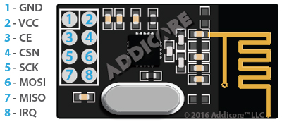
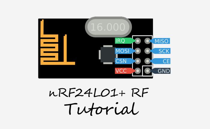
RF模組的引腳佈局如下圖所示。此資訊來源於Addicore。

圖1. nRF24L01+ RF模組的引腳說明 / ©Addicore
根據設定,該RF模組屬於SPI從器件,這意味著它只能與具有專用SPI通信線路的器件一起工作。因此,圖中顯示的SPI MOSI、MISO和SCK(時脈)引腳必須連接到微控制器上的相應引腳。在Arduino上,這些引腳的定義如下:
- MOSI: Arduino D11
- MISO: Arduino D12
- SCK: Arduino D13
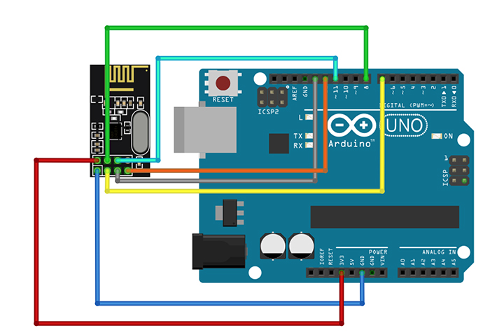
CE和CSN引腳可以連到Arduino上的任何輸出GPIO引腳。在軟體中,SPI通信初始化時系統會指定這些引腳。
RF模組與Arduino之間的連接範例如下:

圖2. CE和CSN引腳(圖中的黃色和綠色線)可以連至任意兩個未使用的數位引腳。在軟體中,您應該在構造RF模組物件時指定這些引腳。
為了連接Arduino與該模組,我們將使用TMRh20的RF24程式館。該程式館能夠方便地將RF模組和MCU之間的低級通信打包成一個易於使用的C++類。
開始使用該模組之前,我們將首先介紹一些背景基礎知識。在美國,射頻裝置能夠使用的頻率僅限於FCC分配的頻率範圍。ISM頻段是為科學和醫療儀器保留的一個頻率範圍,我們的RF模組將使用該ISM範圍內的頻率進行通信。使用RF模組時,我們無需瞭解這些頻率的細節或者通信是如何在這些頻率上發生的。我們將專注於可以控制的無線RF通信內容。
如果滾動瀏覽RF24程式館檔,您會注意到裡面有許多參數可以設定。關鍵參數如下所示:
- 通道: 通信發生的特定頻率通道(頻率映射為0到125之間的整數)
- 讀取通道: 讀取通道是指一個唯一的24位、32位或40位元位址,模組從該位址讀取資料
- 寫入通道: 寫入通道是模組寫入資料的唯一位址
- 功放(PA)級別: PA級別負責設定晶片的功耗,從而設定傳輸功率。就本課程而言(與Arduino一起使用),我們將使用最小功率設定。
RF24程式館文件頁面提供了一些入門的優秀範例代碼。範例項目的位址如下:http://tmrh20.github.io/RF24/examples.html
接下來,我們在“Getting Started”Arduino代碼中查看一下上文列出的參數是如何初始化的。“Getting Started”(入門)代碼的位址如下:
http://tmrh20.github.io/RF24/GettingStarted_8ino-example.html
GettingStarted.ino
|
1 2 3 4 5 6 7 8 9 10 11 12 13 14 15 16 17 18 19 20 21 22 23 24 25 26 27 28 29 30 31 32 33 34 35 36 37 38 39 40 41 42 43 44 45 46 47 48 49 50 51 52 53 54 55 56 57 58 59 60 61 62 63 64 65 66 67 68 69 70 71 72 73 74 75 76 77 78 79 80 81 82 83 84 85 86 87 88 89 90 91 92 93 94 95 96 97 98 99 100 101 102 103 104 105 106 107 108 109 110 111 112 113 114 115 116 117 118 119 120 121 122 123 124 125 126 127 128 129 130 131 132 133 134 135 136 137 138 139 140 141 142 143 144 145 146 147 148 149 150 151 152 153 154 155 156 157 158 159 160 161 162 163 164 165 166 167 168 169 170 171 172 173 174 175 176 177 178 179 180 181 182 183 184 185 186 187 188 189 190 191 192 193 194 195 196 197 198 199 200 201 202 203 204 205 206 207 208 209 210 211 212 213 214 215 216 217 218 219 220 221 222 223 224 225 226 227 |
/* * Getting Started example sketch for nRF24L01+ radios * This is a very basic example of how to send data from one node to another * Updated: Dec 2014 by TMRh20 */ #include <SPI.h> #include "RF24.h" /****************** User Config ***************************/ /*** Set this radio as radio number 0 or 1 ***/ bool radioNumber = 0; /* Hardware configuration: Set up nRF24L01 radio on SPI bus plus pins 7 & 8 */ RF24 radio(7,8); /**********************************************************/ byte addresses[][6] = {"1Node","2Node"}; // Used to control whether this node is sending or receiving bool role = 0; void setup() { Serial.begin(115200); Serial.println(F("RF24/examples/GettingStarted")); Serial.println(F("*** PRESS 'T' to begin transmitting to the other node")); radio.begin(); // Set the PA Level low to prevent power supply related issues since this is a // getting_started sketch, and the likelihood of close proximity of the devices. RF24_PA_MAX is default. radio.setPALevel(RF24_PA_LOW); // Open a writing and reading pipe on each radio, with opposite addresses if(radioNumber){ radio.openWritingPipe(addresses[1]); radio.openReadingPipe(1,addresses[0]); }else{ radio.openWritingPipe(addresses[0]); radio.openReadingPipe(1,addresses[1]); } // Start the radio listening for data radio.startListening(); } void loop() { /****************** Ping Out Role ***************************/ if (role == 1) { radio.stopListening(); // First, stop listening so we can talk. Serial.println(F("Now sending")); unsigned long start_time = micros(); // Take the time, and send it. This will block until complete if (!radio.write( &start_time, sizeof(unsigned long) )){ Serial.println(F("failed")); } radio.startListening(); // Now, continue listening unsigned long started_waiting_at = micros(); // Set up a timeout period, get the current microseconds boolean timeout = false; // Set up a variable to indicate if a response was received or not while ( ! radio.available() ){ // While nothing is received if (micros() - started_waiting_at > 200000 ){ // If waited longer than 200ms, indicate timeout and exit while loop timeout = true; break; } } if ( timeout ){ // Describe the results Serial.println(F("Failed, response timed out.")); }else{ unsigned long got_time; // Grab the response, compare, and send to debugging spew radio.read( &got_time, sizeof(unsigned long) ); unsigned long end_time = micros(); // Spew it Serial.print(F("Sent ")); Serial.print(start_time); Serial.print(F(", Got response ")); Serial.print(got_time); Serial.print(F(", Round-trip delay ")); Serial.print(end_time-start_time); Serial.println(F(" microseconds")); } // Try again 1s later delay(1000); } /****************** Pong Back Role ***************************/ if ( role == 0 ) { unsigned long got_time; if( radio.available()){ // Variable for the received timestamp while (radio.available()) { // While there is data ready radio.read( &got_time, sizeof(unsigned long) ); // Get the payload } radio.stopListening(); // First, stop listening so we can talk radio.write( &got_time, sizeof(unsigned long) ); // Send the final one back. radio.startListening(); // Now, resume listening so we catch the next packets. Serial.print(F("Sent response ")); Serial.println(got_time); } } /****************** Change Roles via Serial Commands ***************************/ if ( Serial.available() ) { char c = toupper(Serial.read()); if ( c == 'T' && role == 0 ){ Serial.println(F("*** CHANGING TO TRANSMIT ROLE -- PRESS 'R' TO SWITCH BACK")); role = 1; // Become the primary transmitter (ping out) }else if ( c == 'R' && role == 1 ){ Serial.println(F("*** CHANGING TO RECEIVE ROLE -- PRESS 'T' TO SWITCH BACK")); role = 0; // Become the primary receiver (pong back) radio.startListening(); } } } // Loop |
首先,我們需要注意檔頂部的兩個C++ #include指令:一個用於包含Arduino SPI程式館(前文提到RF模組使用SPI與Arduino通信),另一個用於包含RF24程式館。
#include <SPI.h>
#include “RF24.h”
接下來,我們需要注意構造RF24物件的這行代碼:RF24 radio(7,8); 傳遞給構造函數的兩個參數是連至模組的CE和CSN數位引腳。MOSI、MISO和SCK引腳必須分別是數位引腳11、12和13,可是CE和CSN引腳可以連接任意兩個數位引腳!
接下來,我們來看一下讀寫通道位址。您可能猜到了,寫入和讀取通道位址在兩個彼此通信的無線裝置之間是互換的,因為一個無線裝置的寫入通道是另一個的讀取通道。無線通訊位址的大小為24位、32位或40位。在範例代碼中,這些位址是從C++字串文字轉換而來,但您也可以以二進位或十六進位格式指定它們。比如,指定為十六進位的40位位址可以是0xF0F0F0F0F0。存儲寫入和讀取通道位址時,一個良好的程式設計實踐是將兩個值放在一個陣列中。在範例代碼中,寫入和讀取通道的位址存儲在名為“位址”的位元組陣列中。
在 void setup() 方法中,我們需要說明如何使用位址通道參數和其他參數初始化無線裝置。
首先,系統調用 RF24::begin() 方法。針對 radio 物件調用其它RF24程式館之方法之前,必須先調用begin() ,這是因為該方法負責初始化RF晶片的運行。
接下來,系統調用 RF24::setPALevel() 方法,以設定功放(PA)級別。為了指定功放級別,RF24程式館提供了不同的常數值。更高的PA級別意味著模組可以實現更長距離的通信,但是在運行期間會消耗更多的電流。作為入門程式,我們將 RF_24_LOW 常數作為一個參數傳遞給 setPALevel() 方法,因為兩個通信模組之間的距離不會很大。一般來講,該RF模組與Arduino板配合使用時,我們應該保持PA級別盡可能地低,從而減少Arduino穩壓電源的電流消耗。
接下來,我們將討論如何初始化寫入和讀取通道。我們已經將寫入和讀取通道定義為一些位元組值。現在,我們必須將這些定義傳遞給 radio 物件,這樣它才會知道寫入和讀取通道位址。系統用 openWritingPipe() 方法設定寫入通道;用 openReadingPipe() 方法設定讀取通道。打開寫入和讀取通道的範例如下:
radio.openWritingPipe(addresses[1]);
radio.openReadingPipe(1, addresses[0]);
請注意,我們還必須為 openReadingPipe() 方法傳遞一個額外的整數參數,指明初始化哪個讀取通道。這是因為RF模組在給定時間最多可以打開6個讀取通道!
範例代碼透過一個role布林值來適當分配讀取和寫入通道值。根據role的值,程式確定RF模組是ping裝置還是pong裝置。您的其他項目也可以使用類似代碼。但是,要確保兩個裝置的讀寫位址互換,否則無法實現資料傳輸或讀取!
調用 RF24::startListening() 方法之後,無線模組開始偵聽。需要注意的是,指示RF模組開始監聽資料之前必須初始化讀取通道(即調用 startListening() 方法之前必須先調用 openReadingPipe() 方法!)
類似地,RF24類還提供了一個 stopListening() 方法,無線模組開始寫入之前必須首先調用該方法。
在範例代碼中,您可能會注意到程式利用 RF24::available() 方法告知無線電模組檢查傳入的資料。這與我們之前見過的 Serial::available() 和 SoftwareSerial::available() 方法類似——如果RF連接上的資料可用,那麼 available() 方法返回真,然後就可以讀取資料了。
最後,RF24類提供了實際資料寫入和讀取的方法。RF24::write() 與 RF24::read() 方法的參數包括(1)指向與傳輸資料類型相同的變數的指標,以及(2)傳輸資料的大小。在 read() 方法中,指標指向的變數負責接收正在讀取的資料。在 write() 方法中,指標指向的變數負責保存正在寫入的資料。在這兩種方法中,我們必須確保指標指向與傳輸資料類型相同的變數,並且傳遞給方法的大小實際上反映了資料的大小。將不正確的類型或大小值傳遞給 read() 和 write() 方法可能會產生不希望的值截斷,從而導致傳輸的資料無用。在“Getting Started”代碼中,需要傳輸的資料是一個 unsigned long 類型。因此,傳遞給 read() 和 write() 方法的指標參數也應該指向一個 unsigned long 型的變數。很明顯,傳輸資料的大小始終是unsigned long類型變數的大小。在這種情況下,大小並不需要用一個整數進行傳遞,大小(size)參數可以簡單地寫為sizeof(unsigned long)。
“Getting Started”(入門)代碼中唯一沒有涉及的參數是通道(communication channel)。如果需要指定具體通道(比如您有多個RF網路,不希望彼此干擾),那麼可以將一個8位元的整數參數傳遞給 RF24::setChannel() 方法,以設定通道。其代碼範例如下:radio.setChannel(10);
請將兩個RF模組連到兩個獨立的Arduino板上,並且都上傳“Getting Started”(入門)代碼(您必須將其中一塊板的 role 布林值改為1)。您現在應該能夠根據相應的ping時間發送消息並且接收返回的消息了!下圖是“ping”和“pong”兩個串口監視器的並排截圖:

圖3. 左:“ping”監視器語句(裝置1);右:“pong”監視器語句(裝置0)
恭喜您完成nRF24L01+課程的學習!您現在已經掌握了使用這些漂亮RF模組研發相關專案的技能和知識了!要瞭解涉及這些RF模組的專案,您可以瀏覽Device Plus部落格!


