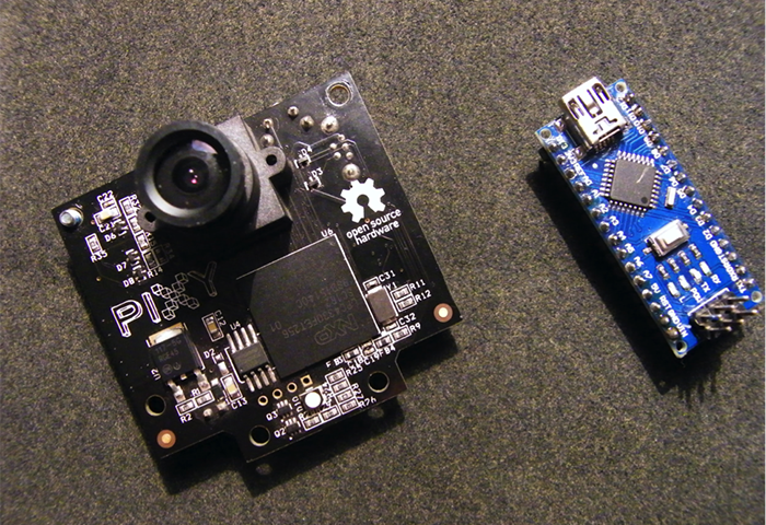
CMUcam5 Pixy視覺相機感測器簡介 第二部分–創建球平衡梁
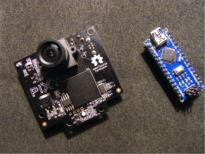
這是CMUcam5 Pixy簡介的第二部分。如果您對PixyMon不太熟悉,請先回顧CMUcam5 Pixy視覺相機感測器簡介。在第一部分中,我介紹了Pixy的基礎知識,解釋了hello_world代碼,並創建了一個簡單的伺服驅動的應用程式。在本課程中,我將進一步探索Pixy的應用,創建一個球平衡梁。透過一個伺服來設定平衡梁的角度,使球停留在中間,當然,Pixy相機感測器會對球進行追蹤。
硬體
- Arduino Uno(您可以使用任何Arduino)
- CMUcam5 Pixy 相機
- 伺服馬達 (S06NF)
- 木片和螺絲
- 資料線 (用於相機USB MINI 以及Uno USB B)
- 用於伺服的5V外部電源(!警告!如果您將伺服連接到Arduino透過USB進行供電,您的Arduino將會被燒壞)
軟體
- Arduino IDE 1.6.9
- PixyMon 軟體 (http://cmucam.org/projects/cmucam5/wiki/Install_PixyMon_on_Windows_Vista_7_8)
- PixyMon 用於 Arduino 的程式館 (http://cmucam.org/projects/cmucam5/wiki/Latest_release)
- Processing 3.1.1 (https://processing.org/download/?processing)
Processing的簡單介紹

Processing是非常有用又靈活的一款軟體。它主要用於視覺藝術和科技領域的視覺語言。這款軟體具有100多個程式館,可支援各種項目。它的文件非常齊全,提供了許多使用指南,涵蓋了從程式設計基礎到視覺化等各種主題。它能夠支援所有作業系統(GNU/Linux, Mac OS X, 和 Windows)。該軟體的設計幾乎和Arduino IDE相同。
今天,我們將使用Processing,透過序列通信實現與Arduino之間的通信。
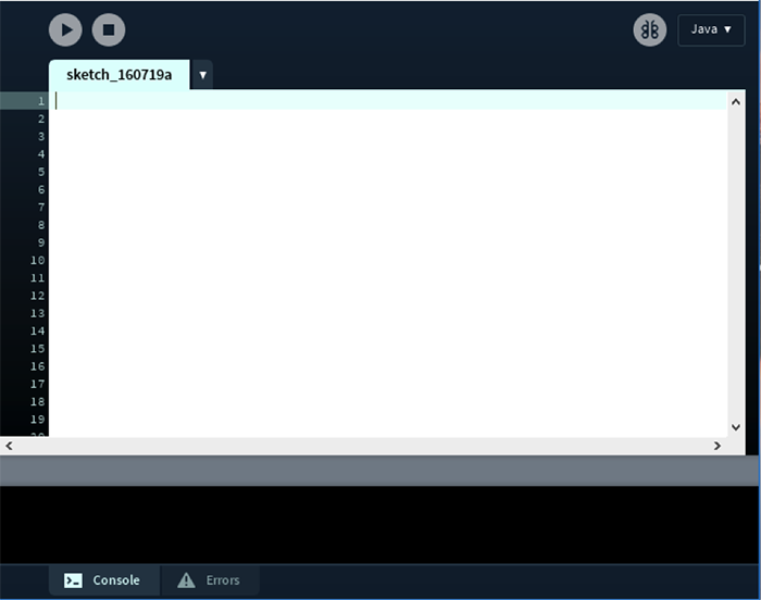
圖1:Processing介面
項目概況
在此項目中,我將製作一個球平衡梁,一個用木頭製成的“通道”將會像一桿秤那樣使球保持平衡(圖2)。平衡梁44cm寬,3cm高。我把它製造的像通道一樣狹窄,使我們所追蹤的球不會掉落出去。
我使用S06NF伺服馬達來行動整個平衡梁,該馬達由Arduino進行控制。之後我們會看一下在本課程後面部分的代碼。現在,我已經將伺服放置在了距離平衡梁左端¼的位置。
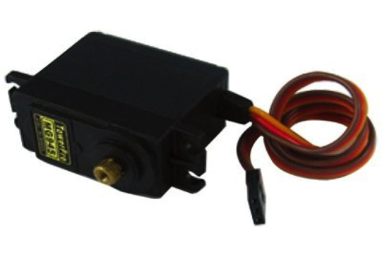
圖2:S06NF STD 伺服馬達/ ©RobotShop inc.
伺服將上下行動平衡梁,同時,球也會沿著該路徑行動。
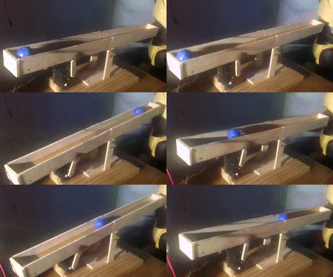
圖3:平衡梁上下行動
數位相機將會放置在平衡梁上。我將相機的視野範圍設定為僅限於平衡梁。這樣,相機就會只追蹤球,不追蹤任何其他物體了。
平衡梁結構
首先,我們需要一些用於構建平衡梁的材料。我將要使用的是一種簡單的XXMM木材(20cm x 27cm)。我用圓鋸來切割木材,但是您可以使用現有的任何類型的鋸來完成切割,只要能夠保障切割面平整、均勻即可。
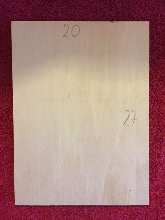
圖4:XXMM木材
請記住,只有使用正確的工具才能夠製造出完美的平衡梁!我使用的是一把錘子、一把直尺、釘子、砂紙、熱膠、一個鑽頭和一把鋸子。
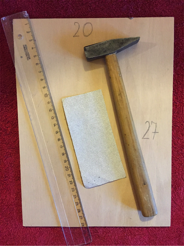
圖5:工具
首先,我將製造一個通道,使球能夠在其中左右行動。通道的側面由四塊木板組成(每個21cm x 3cm)。通道在高度方向的兩端將由兩塊木板(4cm x 3cm)封接。底座的尺寸是42cm x 3cm x 1cm。
我使用15mm大帽釘來連接零零件。
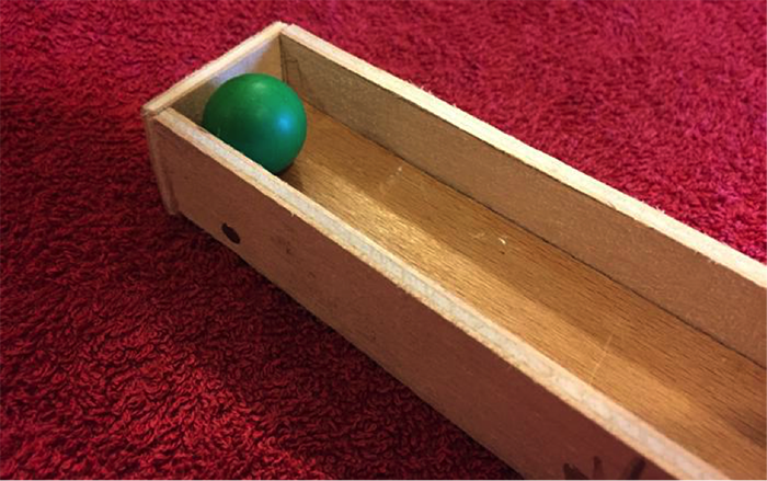
圖6:封閉通道
在通道中間建立傾斜點有很多種方法。我使用了一種非常簡單的方法,因為成本最低且最容易實現。我用了一個長釘子,兩個像軸承一樣的小管子,先標記了通道的中心點,然後將這些小軸承熱粘合到該中心點,再插入釘子。
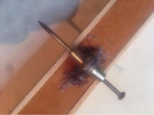
圖7:用於構建傾斜點的釘子和管子
為了設定傾斜點,我們還需要為釘子製作支架。我用了兩塊8cm x 2cm的木板,如圖8所示。我還製作了一個小平台,可以將所有東西放置在一起,尺寸為12cm x 4.5cm。
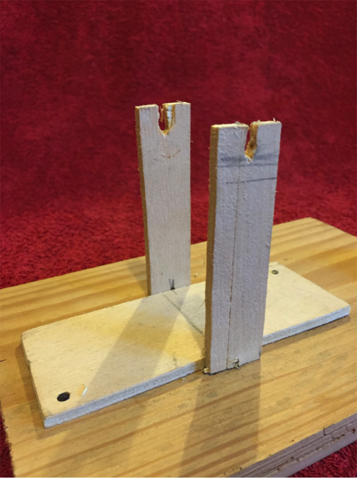
圖8:傾斜點支架
我使用了一小塊木材來安裝伺服並將其架起。
圖9:安裝在木板上的伺服
在本課程中我使用的是Arduino UNO,但是您也可以使用其他具有SPI連接器的Arduino來連接到Pixy相機。
連接所有零件
一旦構建完成,下一步就是將Pixy相機連接到Arduino,然後再連接到伺服。原理圖與CMUcam5 Pixy視覺相機感測器簡介中的相同。我仍然使用外部5V電源為伺服供電。
!警告! 不要忘記連接接地端。如果沒有將電源、伺服和Arduino接地端相連接,伺服將會失控!
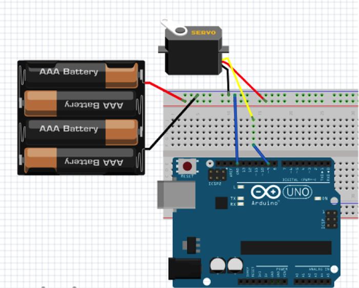
圖10:接線圖
接下來,我需要在平衡梁結構上方的某個位置設定Pixy,以便它可以隨時檢測到球的位置。調整設定使其僅可以對球進行檢測。請參考第一部分進行設定。
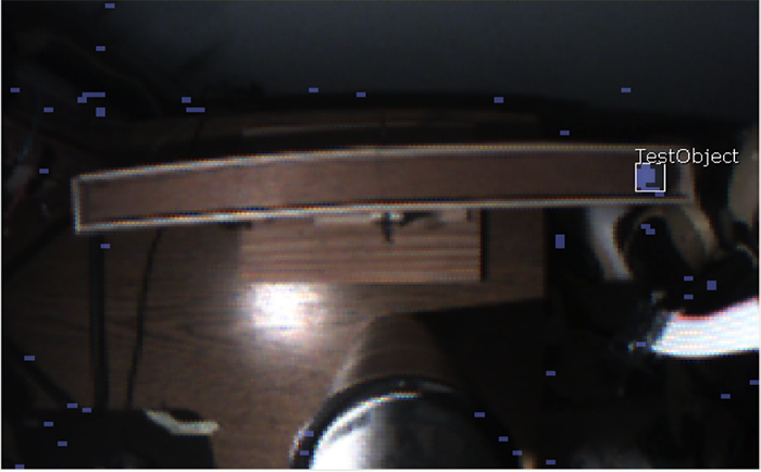
圖11:Pixy視覺
現在,讓我們來看一些代碼。為了檢測伺服是否工作正常,我修改了中間、最右邊和最左邊的角度,使其適合於我的結構。
|
1 2 3 4 5 6 7 8 9 10 11 12 13 14 15 16 17 18 19 20 21 22 23 24 25 26 27 28 29 30 31 |
#include <Servo.h> uint8_t leveled = 110; //middle positon for s1 to keep the board leveled uint8_t far_right = 180; //far left positon for s1 to keep the board leveled uint8_t far_left = 0; //far right positon for s1 to keep the board levele Servo s; void setup(){ s.write(leveled); delay(2000); s.write(far_right); delay(2000); s.write(far_left); delay(2000); } void loop(){ } |
當然,您可以根據自己的喜好來調整變數。
之前,我介紹了一個名叫Processing的軟體。我將使用它透過序列通信來實現與Arduino的通信。
Arduino 代碼
簡單的序列通信:
|
1 2 3 4 5 6 7 8 9 10 11 12 13 14 15 16 17 18 19 20 21 22 |
#include #include char val; // Data received from the serial port int ledPin = 13; // Set the pin to digital I/O 13 void setup() { pinMode(ledPin, OUTPUT); // Set pin as OUTPUT Serial.begin(9600); // Start serial communication at 9600 bps } void loop() { if (Serial.available()) { // If data is available to read, val = Serial.read(); // read it and store it in val } if (val == '1') { // If 1 was received digitalWrite(ledPin, HIGH); // turn the LED on } else { digitalWrite(ledPin, LOW); // otherwise turn it off } delay(10); // Wait 10 milliseconds for next reading } |
Processing 代碼
|
1 2 3 4 5 6 7 8 9 10 11 12 13 14 15 16 17 18 19 20 |
import processing.serial.*; Serial myPort; // Create object from Serial class void setup() { size(200,200); //make our canvas 200 x 200 pixels big String portName = Serial.list()[0]; //change the 0 to a 1 or 2 etc. to match your port myPort = new Serial(this, portName, 9600); } void draw() { if (mousePressed == true) { //if we clicked in the window myPort.write('1'); //send a 1 println("1"); } else { //otherwise myPort.write('0'); //send a 0 } } |
改代碼創建了一個200×200像素的視窗並初始化序列埠。draw()空函數用於檢查是否在視窗上按下了滑鼠(如果按下寫入1,沒有按下則寫入0)。
現在,我們來測試代碼。點擊運行,然後嘗試點擊視窗中任意位置,這時您的LED燈應發生閃爍,這就表示著一切工作正常!

圖12:Processing 和 Arduino代碼的基本測試
使用Processing程式設計
我獲取了伺服的相關值,並在Processing中對其進行了處理,所以產生了一個類似於下圖所示的圖片。
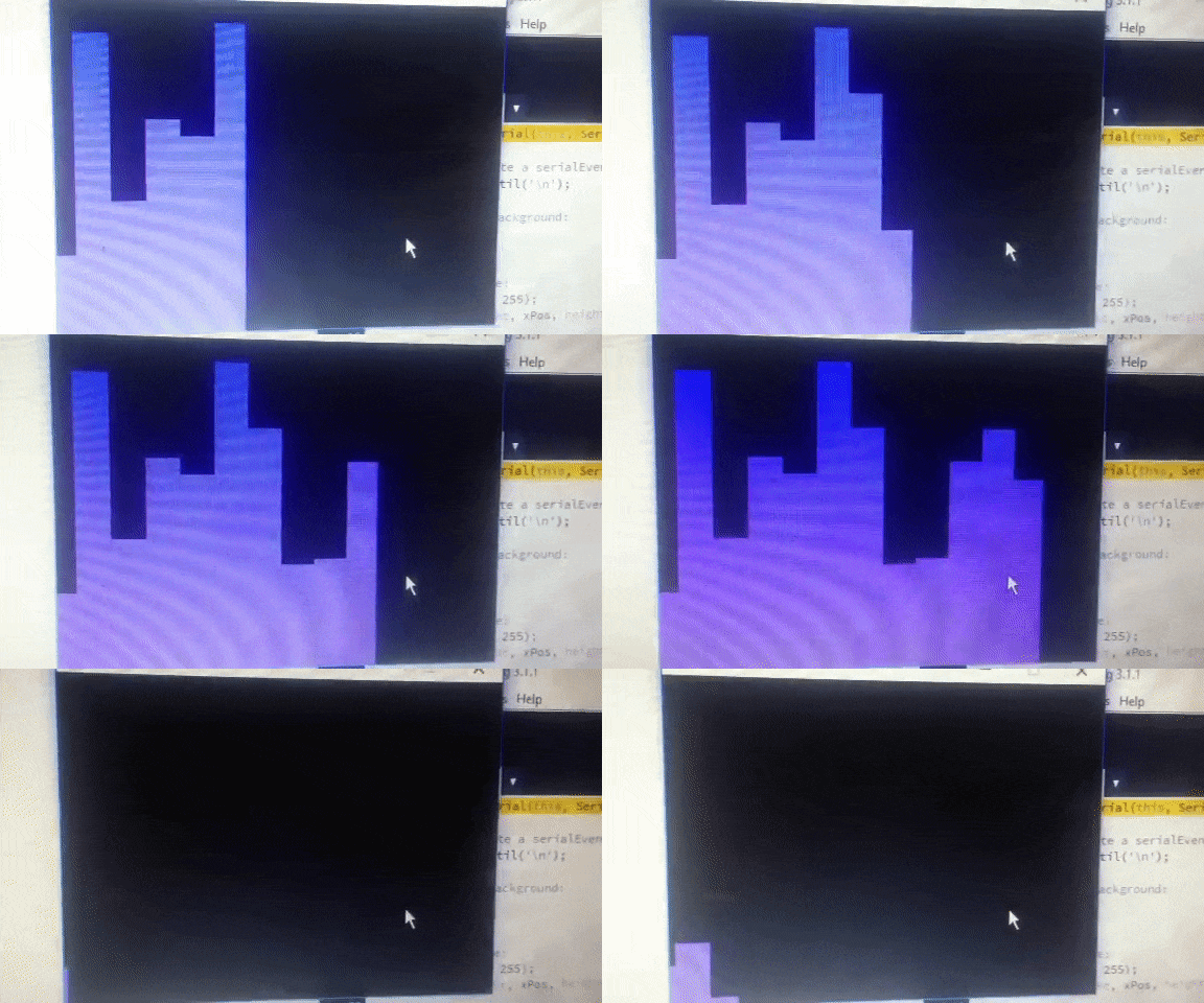
圖13:範例圖片
請用以下代碼創建圖像:
|
1 2 3 4 5 6 7 8 9 10 11 12 13 14 15 16 17 18 19 20 21 22 23 24 25 26 27 28 29 30 31 32 33 34 35 36 37 38 39 40 41 42 43 44 45 46 47 48 49 50 51 52 53 54 |
import processing.serial.*; Serial myPort; // The serial port int xPos = 1; // horizontal position of the graph float inByte = 0; void setup () { // set the window size: size(400, 300); // List all the available serial ports // if using Processing 2.1 or later, use Serial.printArray() println(Serial.list()); // I know that the first port in the serial list on my mac // is always my Arduino, so I open Serial.list()[0]. // Open whatever port is the one you're using. myPort = new Serial(this, Serial.list()[0], 9600); // don't generate a serialEvent() unless you get a newline character: myPort.bufferUntil('\n'); // set inital background: background(0); } void draw () { // draw the line: stroke(127, 34, 255); line(xPos, height, xPos, height - inByte); // at the edge of the screen, go back to the beginning: if (xPos >= width) { xPos = 0; background(0); } else { // increment the horizontal position: xPos++; } } void serialEvent (Serial myPort) { // get the ASCII string: String inString = myPort.readStringUntil('\n'); if (inString != null) { // trim off any whitespace: inString = trim(inString); // convert to an int and map to the screen height: inByte = float(inString); println(inByte); inByte = map(inByte, 0, 1023, 0, height); } } |
Arduino 代碼:
|
1 2 3 4 5 6 7 8 9 10 11 12 13 14 15 16 17 18 19 20 21 22 23 24 25 26 27 28 29 30 31 32 33 34 35 36 37 38 39 40 41 42 43 44 45 46 47 48 49 50 51 52 53 54 55 56 57 58 59 60 61 62 63 64 65 66 67 68 69 70 71 72 73 74 75 76 77 78 79 80 81 82 83 84 85 86 87 88 89 90 91 92 93 94 95 96 97 98 99 100 101 102 |
#include #include #include #include //37 164 288 uint8_t leveled = 110; //middle positon for s1 to keep the board leveled uint8_t far_right = 180; //far left positon for s1 to keep the board leveled uint8_t far_left = 0; //far right positon for s1 to keep the board levele int current_pos = leveled; int percentage,var,_percen; Servo s; Pixy pixy; void test_board(){ while(Serial.read() != 'b'); Serial.write("Starting test"); s.write(leveled); delay(2000); s.write(far_right); delay(2000); s.write(far_left); delay(2000); Serial.write("Finished test, press any key to continue"); while(Serial.read() != 'c'); s.write(current_pos); Serial.write("Continued"); } void setup() { Serial.begin(9600); s.attach(9); pixy.init(); while (!Serial); //test_board(); s.write(current_pos); } void _servo(unsigned char side,int var){ //by the % we get how "hard" we need to wip :D var = var - 90; if(side == 'L'){ //Serial.write("LEFT"); //90 180 _percen = 90 + var; s.write(_percen); }else{ //Serial.write("RIGHT"); //0 90 _percen = 90 - var; s.write(_percen); } } void loop() { static int i = 0; int j; uint16_t blocks; char buf[32]; // grab blocks! blocks = pixy.getBlocks(); // If there are detect blocks, print them! if (blocks) { i++; // do this (print) every 50 frames because printing every // frame would bog down the Arduino if (i%1 ==0) { //sprintf(buf, "Detected %d:\n", blocks); //Serial.print(buf); for (j=0; j<blocks; j++) { //sprintf(buf, " block %d: ", j); //Serial.print(buf); // pixy.blocks[j].print(); uint32_t x_pos= pixy.blocks[j].x; //Serial.write(x_pos); percentage = (x_pos - 35) / 2.5; if(percentage <= 40 && percentage >= 0){ // Serial.write("LEFT"); var = percentage / 0.4; _servo('L',var); }else if(percentage >= 60 && percentage <= 110){ //Serial.write("RIGHT"); var = (percentage - 60) / 0.5; _servo('R',var); }else{ //Serial.write("MIDDLE"); } } } } } |
代碼釋義
我將x的位置從Pixy轉換為0-100%,並由此瞭解球的具體位置。透過獲取球的位置,我可以調整伺服轉速。如果球的位置 <=10%,伺服會轉得更快來維持平衡;如果在~40%附近,伺服會以很低的轉速來維持平衡。想要一直保持平衡是比較棘手的,我們可以改進演算法以使其更加精確。
以下是一些有益於提升的建議:
- 嘗試多種演算法
- 有多種類型的數學演算法可以進行計算。我至少嘗試了兩到三種,但是最後決定選擇該演算法。我建議您自己來編寫演算法,以更好地掌握這種平衡的方法。
- 更好的硬體
- 對於本項目來說,沒有什麼材料可稱得上是完美的,木材就更差得遠了。如果我擁有及時可用的資源,那我會選擇用金屬來建造它,這樣整個項目將會更加穩定和精確。
- 變得更快
- 我們如何做到使其更快地恢復平衡?我在這裡使用了一個簡單的伺服。我們可以將其替換為UART或者AX-12之類的伺服,它們會強大、快速得多。速度也與演算法有關。同樣,我建議您嘗試不同的演算法,以找到適用於您的目的的演算法。
有許多項目使用類似的概念來對平衡某物體。除了Pixy,您還可以將OpenCV與任何網路相機一起使用來檢測目標和顏色。除了Processing,還有Max/MSP版本5。您可以使用距離感測器、壓力感測器等。因此,有多種方式可以説明您對該項目進行提升,使其更加堅固、穩定和更快。


