如何在Raspberry Pi運行Arduino程式
高級範例:SPI和I2C
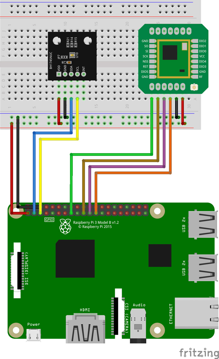
顯然,LED閃爍和控制台輸出等功能可以完成許多不錯的專案,但是我認為,如果添加一些更高級的功能,比如I2C和SPI,我們就可以做更多事情。RasPiArduino框架同樣支援這些功能,所以我們可以用I2C匯流排將不同的感測器連至Raspberry;或者讓Raspberry透過SPI匯流排與各通信模組進行通信。對於I2C器件,我使用的是羅姆感測器評估套件 中的BH1745NUC顏色感測器;對於SPI,我用的是SX1278 LoRa模組。這兩者的運行電壓邏輯都是3.3V,因此只需幾根線纜就可以將它們與Raspberry連接起來,非常簡單。

圖12 本例的接線示意圖
多虧了LoRaLib和RohmMultiSensor程式館,系統代碼也非常簡單!基本上就是LoRaLib程式館中的接收器範例代碼加上RohmMultiSensor程式館中的BH1745NUC範例代碼。
|
1 2 3 4 5 6 7 8 9 10 11 12 13 14 15 16 17 18 19 20 21 22 23 24 25 26 27 28 29 30 31 32 33 34 35 36 37 38 39 40 41 42 43 44 45 46 47 48 49 50 51 52 53 54 55 56 57 58 59 60 61 62 63 64 65 66 67 68 69 70 71 72 73 74 75 76 77 78 79 80 81 82 83 84 85 86 87 88 89 90 91 92 93 94 |
// define the sensor we will use #define INCLUDE_BH1745NUC // include the libraries #include <RohmMultiSensor.h> #include <LoRaLib.h> // instantiate the sensor's class BH1745NUC sensorColor; // SX1278 digital I/O pin 0 int dio0 = 17; // SX1278 digital I/O pin 1 int dio1 = 27; // SX1278 SPI slave select pin int nss = 22; // create LoRa class instance LoRa lora(CH_SX1278, nss, BW_125_00_KHZ, SF_9, CR_4_7, dio0, dio1); // create empty instance of Packet class Packet pack; void setup() { // start I2C communication Wire.begin(); // initialize LoRa uint8_t state = lora.begin(); if(state == ERR_NONE) { Console.println("[SX1278]\tInitialization done."); } else { Console.print("[SX1278]\tInitialization failed, code 0x"); Console.println(state, HEX); while(true); } // initialize the sensor with default settings state = sensorColor.init(); if(state == 0) { Console.println("[BH1745]\tInitialization done."); } else { Console.print("[BH1745]\tInitialization failed, code 0x"); Console.println(state, HEX); while(true); } Console.println("-------------------------------------------------------------------"); } void loop() { Console.print("[SX1278]\tWaiting for incoming transmission ... "); // wait for single packet uint8_t state = lora.receive(pack); if(state == ERR_NONE) { // packet was suceesfully received Console.println("success!"); // print the data of the packet Console.print("[SX1278]\tData:\t\t"); Console.println(pack.data); } else if(state == ERR_RX_TIMEOUT) { // timeout occured while waiting for a packet Console.println("timeout!"); } else if(state == ERR_CRC_MISMATCH) { // packet was received, but is malformed Console.println("CRC error!"); } Console.println("-------------------------------------------------------------------"); Console.print("[BH1745]\tColor Values (R-G-B-C):\t"); // measure the sensor values sensorColor.measure(); // print the values to the console Console.print(sensorColor.red); Console.print('\t'); Console.print(sensorColor.green); Console.print('\t'); Console.print(sensorColor.blue); Console.print('\t'); Console.println(sensorColor.clear); Console.println("-------------------------------------------------------------------"); } |
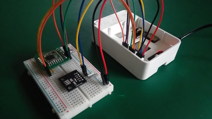
電路實物如下圖所示。雖然不漂亮,但是很實用。

圖13 已連接SX1278無線模組和BH1274NUC顏色感測器的Raspberry Pi
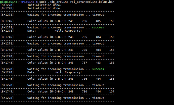
在此範例中,所有重要資訊都被列印到Raspberry控制台。我們可以看到,SX1278成功接收到了包含字串“Hello Raspberry!”的資料包(從Arduino透過LoRenz研發板發送),而且顏色感測器測量的值也是正確的!

圖14 Raspberry Pi控制台輸出
結論
那麼結論是:我們可以將Raspberry Pi當作Arduino研發板進行程式設計嗎?絕對可以!但是,這兩種系統都有優缺點。Raspberry的處理速度更快,Arduino功耗更低;Raspberry具有內建的HDMI和乙太網埠,而Arduino具有內建的模數轉換器。其他對比不再一一列舉。但是,這歸根結底是因為Arduino和Raspberry的應用場景不同。比如,如果您需要構建基於電池的感測器監控系統,請選Arduino。如果您需要透過機器學習來處理相機圖片,請選Raspberry Pi。總之,我們必須根據系統要處理的任務類型選擇適當元件,反之則不行。


