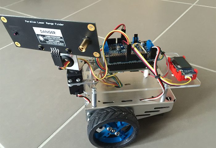
利用Parallax雷射感測器製作Arduino雷射機器人—第2部分
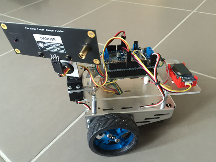
在第1部分中,我們製作了一塊客製化的壓克力板底座,把NEMA 17步進馬達安裝到了底盤上。然後,我們將Arduino Uno 3和馬達研發板也連到壓克力底座上,並安裝了馬達研發板程式館。在第2部分中,我們將添加機器人工作所需的其他系統零件,比如伺服器和雷射測距儀(LRF),並編寫一個程式,讓機器人能夠自主行動。
有關如何利用Arduino UNO R3從零開始搭建輪式機器人的資訊,請參考我們在之前的文章《如何製作自己的機器人》和《如何製作自己的機器人(第2部分)》。在本文中,我們將進一步增加機器人的功能:讓該機器人動起來並為其增加雷射測距(LRF)功能,以使該裝置能夠檢測物體並測量距離。
該機器人的設計目標如下:
- 向前、向後行動;向左和向右旋轉90度;向左和向右旋轉45度。
- 避開障礙物時根據最佳可用路徑朝不同的方向行動。
- 測量各個方向(前方、左右90度、左右45度)的距離。
- 根據可用的最長距離,確定朝哪個方向前進(向前、向後、向左或向右)。
硬體
製作此機器人所需的硬體請參見以下硬體明細,這些零零件在許多電商網站都可以買到(明細中給出了部分位址)。
- Arduino Uno rev 3 (www.adafruit.com/products/50)
- 適用於Arduino的Adafruit步進馬達研發套件 (www.adafruit.com/products/1438)
- 步進馬達 (www.adafruit.com/products/324)
- 底盤、螺絲和尾輪 Parallax.com
- 車輪、 橡膠輪胎和輪轂 Makeblock.com
- 伺服裝置和安裝套件 (www.parallax.com/product/570-28015)
- Parallax 雷射測距儀 (www.parallax.com/product/28044)
- OLED 顯示幕 (www.seeedstudio.com/Grove-OLED-Display-1.12”-p-824.html)
- 紅色封裝紙/盒 (http://www.seeedstudio.com/Grove-Red-Wrapper-1*2(4-PCS-pack)-p-2585.html)
- 鋰聚合物電池3型(11.1V)和連接器 (http://www.hobbyking.com/hobbyking/store/__18203)
- 195 x 195 x 3mm壓克力板 (http://www.jaycar.com.au/clear-acrylic-sheet/p/HM9509)
軟體
- Arduino IDE
- Adafruit Motor Shield Library
- LCD Display9696 Library.zip
工具
- 圓銼
- Dremel 電動工具
- 電烙鐵
- 迷你鋼鋸
安裝並測試伺服器
下一步是安裝用於平移的伺服器。首先,請用螺釘將兩塊小板擰到伺服基座上,然後用螺釘將其固定到壓克力底座上,如圖1和圖2所示。請用2個螺釘將鋁制安裝架安裝到伺服器的頂部。
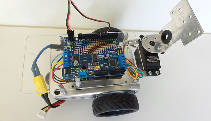
圖1. 用兩小板將伺服器固定到壓克力底座上
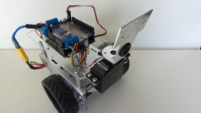
圖2. 將鋁制安裝架安裝到伺服器上
如圖3所示,將伺服器的連接器連至馬達研發板。馬達研發板上有2個伺服器連接器,分別標記為“servo1”和“servo2”。本次連接請使用servo1連接器(外側的那個)。請注意,切勿接反。
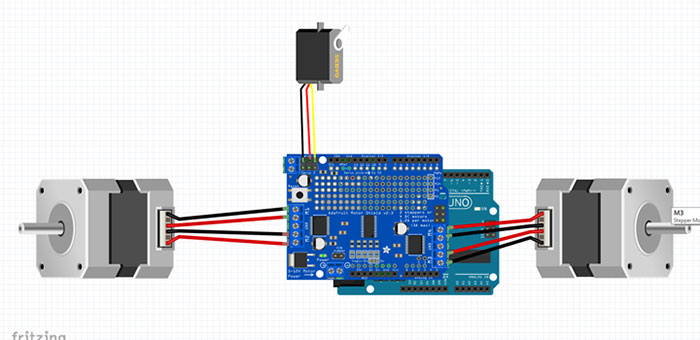
圖3. 伺服與馬達研發板的連接
現在,我們可以運行程式了,請將以下代碼上傳到Arduino。無需安裝新程式館,系統所需的程式館(Servo.h)都已包含在Arduino IDE程式中。伺服器應使用Digital引腳10(servo 1),或者如果伺服器連接到馬達研發板的servo 2,那麼應使用引腳11。
|
1 2 3 4 5 6 7 8 9 10 11 12 13 14 15 16 17 18 19 20 21 22 23 24 25 26 27 28 29 30 31 32 33 34 35 36 37 38 39 40 41 42 43 44 45 46 47 |
//*********************************************************************************************** #include <Servo.h> Servo panMotor; // servo for laser range finder (lrf) scanning int pos = 0; // variable to store the servo position const int a = 1000; void setup() { panMotor.attach(10); } // Attach Servo for scanning to pin 10 void loop() { // *************************** Scan Left *********************************** panMotor.write(180); // 90 degree delay(a); panMotor.write(135); // 45 degree delay(a); // ************************** Scan Right ********************************** panMotor.write(45); // 45 degree delay(a); panMotor.write(0); // 90 degree delay(a); // ************************* Neutral position ***************************** panMotor.write(90); delay(a); } //************************************************************************************************** |
代碼很簡單,它負責讓機器人從左向右進行掃描並返回原始位置。
伺服器的工作原理請參見以下視訊:
安裝雷射測距儀 (LRF)
雷射測距儀產品文件 – Parallax
Parallax雷射測距儀(LRF)模組是一款利用雷射技術計算儀器到目標物體的距離的測量儀器。該裝置根據光學三角測量法(雷射、相機和物體質心之間的簡單三角函數)來計算儀器到目標物體的距離。其最佳測量範圍為6–48英寸(15–122公分),測量精度誤差<5%(平均3%)。
硬體安裝很簡單。只需在壓克力板上鑽兩個與LRF位置相匹配的孔,然後用塑膠墊片和螺釘將LRF固定到鋁底盤上即可(請參見圖5)。
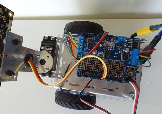
圖4. 將LRF電纜連至馬達研發板
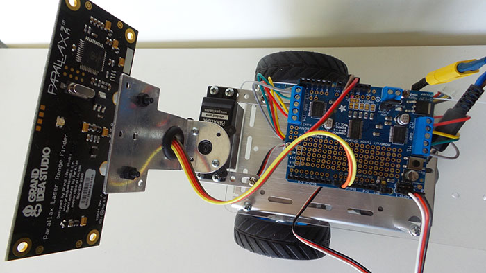
圖5. 安裝在鋁制安裝架上的LRF
由於LRF的最佳測量值上限為122公分,我們需要將鋁制安裝架稍微向前彎曲,以使該範圍始終小於120公分(圖6)。

圖6. 向前彎曲鋁制安裝架,使雷射到地的距離小於120公分
請完全按照圖7將電纜連接器連至LRF。GND接地,VCC接5V,SOUT接引腳8,SIN接引腳9。
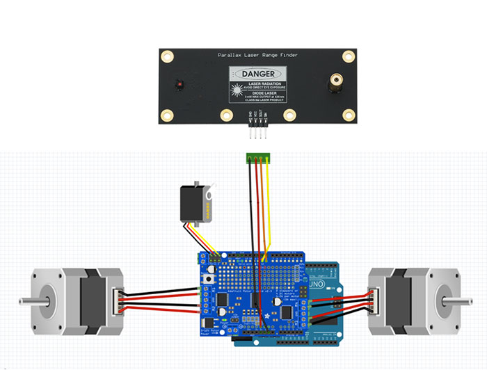
圖7. LRF與馬達研發板的連接
我們已經完成了LRF的安裝和連接,現在就來上傳代碼吧!同樣,無需安裝程式館。我們要用的SoftwareSerial.h已經包含在Arduino IDE中。
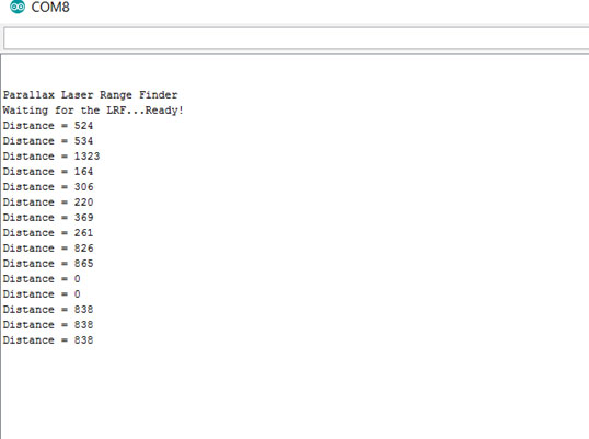
下面的代碼源自範例代碼,我們只是進行了一些修改,將距離資料從字串轉換為整數。其作用是測量感測器到前方物體的距離並列印結果。我們用序列監視器顯示結果。
|
1 2 3 4 5 6 7 8 9 10 11 12 13 14 15 16 17 18 19 20 21 22 23 24 25 26 27 28 29 30 31 32 33 34 35 36 37 38 39 40 41 42 43 44 45 46 47 48 49 50 51 52 53 54 55 56 57 58 59 60 61 62 63 64 65 66 67 68 69 70 71 72 73 74 75 76 77 78 79 80 81 82 83 84 85 86 87 88 89 90 91 92 93 94 95 96 97 98 99 100 101 102 103 104 105 106 107 108 109 110 111 112 113 114 115 116 117 118 119 120 121 122 123 124 125 126 127 128 129 130 131 132 133 134 135 136 137 138 139 140 141 |
// ************************************************************************************************************************************************** #include <SoftwareSerial.h> #define rxPin 8 // Serial input (connects to the LRF's SOUT pin) #define txPin 9 // Serial output (connects to the LRF's SIN pin) #define ledPin 13 // Most Arduino boards have an on-board LED on this pin #define BUFSIZE 16 // Size of buffer int lrfDataInt; SoftwareSerial lrfSerial = SoftwareSerial(rxPin, txPin); void setup() // Set up code called once on start-up { // *************************************** setup for LRF *********************************************** pinMode(ledPin, OUTPUT); pinMode(rxPin, INPUT); pinMode(txPin, OUTPUT); digitalWrite(ledPin, LOW); // turn LED off Serial.begin(9600); while (!Serial); // Wait until ready Serial.println("\n\nParallax Laser Range Finder"); lrfSerial.begin(9600); Serial.print("Waiting for the LRF..."); delay(2000); // Delay to let LRF module start up lrfSerial.print('U'); // Send character while (lrfSerial.read() != ':'); delay(10); // Short delay lrfSerial.flush(); // Flush the receive buffer Serial.println("Ready!"); Serial.flush(); // Wait for all bytes to be transmitted to the Serial Monitor } // ****************************************** main loop ************************************************ void loop() // Main code, to run repeatedly { lrf(); } // ****************************************** end main loop ********************************************* void lrf() { lrfSerial.print('R'); // Send command digitalWrite(ledPin, HIGH); // Turn LED on while LRF is taking a measurement char lrfData[BUFSIZE]; // Buffer for incoming data int lrfDataInt1; int lrfDataInt2; int lrfDataInt3; int lrfDataInt4; int offset = 0; // Offset into buffer lrfData[0] = 0; // Clear the buffer while(1) { if (lrfSerial.available() > 0) // If there are any bytes available to read, then the LRF must have responded { lrfData[offset] = lrfSerial.read(); // Get the byte and store it in our buffer if (lrfData[offset] == ':') // If a ":" character is received, all data has been sent and the LRF is ready to accept the next command { lrfData[offset] = 0; // Null terminate the string of bytes we just received break; } // Break out of the loop offset++; // Increment offset into array if (offset >= BUFSIZE) offset = 0; // If the incoming data string is longer than our buffer, wrap around to avoid going out-of-bounds } } lrfDataInt1 = ( lrfData[5] -'0'); lrfDataInt2 = ( lrfData[6] -'0'); lrfDataInt3 = ( lrfData[7] -'0'); lrfDataInt4 = ( lrfData[8] -'0'); lrfDataInt = (1000*lrfDataInt1)+ (100*lrfDataInt2)+(10*lrfDataInt3) + lrfDataInt4; Serial.print("Distance = "); // The lrfData string should now contain the data returned by the LRF, so display it on the Serial Monitor Serial.println(lrfDataInt); Serial.flush(); // Wait for all bytes to be transmitted to the Serial Monitor digitalWrite(ledPin, LOW); // Turn LED off delay(1000); } //************************************************************************************************************************************************* |
序列監視器顯示的結果如下所示。所有尺寸的單位均為毫米。
安裝OLED顯示幕
首先,我們將OLED塑膠盒安裝到壓克力底座中(請參見圖9),然後再將OLED顯示幕附帶的線纜一端連至顯示幕。要將顯示幕連至馬達研發板,請將線纜另外一端jst連接器上的線纜剪下,然後將紅導線焊至5V,將黑導線焊至Ground,將黃導線焊至SDA引腳,將綠導線焊至SCL引腳。請確保OLED顯示幕的背面朝外。
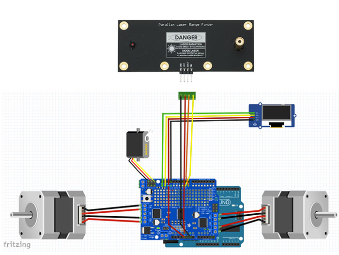
圖8 . OLED與馬達研發板之間的連接
將OLED固定在底座上並連接電纜後,我們就可以運行部分軟體了。
首先,請確保已經安裝了SeeedOLED.h 程式館。然後,將以下代碼上傳到Arduino。該代碼使用了名為oled1的函數,稍後的最終編碼也會使用該函數。其基本功能就是顯示100到109的數位。
|
1 2 3 4 5 6 7 8 9 10 11 12 13 14 15 16 17 18 19 20 21 22 23 24 25 26 27 28 29 30 31 32 33 34 35 36 37 38 39 40 41 42 43 44 45 46 47 48 49 |
//***************************************************************************************************************************************** #include <Wire.h> #include <SeeedOLED.h> int distanceFwd; void setup() { Wire.begin();} void loop() { int i = 0; for (i; (i < 10); i ++) { distanceFwd = 100 + i; oled1(); delay(1000); } } void oled1() { SeeedOled.clearDisplay(); //clear the screen and set start position to top left corner SeeedOled.setNormalDisplay(); //Set display to Normal mode SeeedOled.setPageMode(); //Set addressing mode to Page Mode SeeedOled.setTextXY(3,3); SeeedOled.putString("Forward :"); SeeedOled.setTextXY(5,9); SeeedOled.putNumber(distanceFwd); } //***************************************************************************************************************************************** |
程式正常運行時,顯示幕應該會顯示以下視訊中的內容:
安裝最終代碼
現在,我們已經完成了所有硬體的安裝並測試了各個裝置。讓我們把所有軟硬體結合起來,構建一個可以自主行動的智慧雷射機器人吧。最終程式會執行以下功能:
- 測量前方距離:
- 如果距離超過70公分,機器人將向前行動500步(大約50公分);
- 如果距離大於40公分小於70公分,機器人將向前行動200步(20公分);
- 如果距離小於40公分,機器人會向左掃描90度,向左掃描45度,向右掃描45度,向右掃描90度;
- 測量每個方向的距離,然後計算哪個方向的測量距離最長;
- 轉向距離最長的那個方向;
- 返回第一步。
請複製以下代碼並將其上傳到Arduino:
|
1 2 3 4 5 6 7 8 9 10 11 12 13 14 15 16 17 18 19 20 21 22 23 24 25 26 27 28 29 30 31 32 33 34 35 36 37 38 39 40 41 42 43 44 45 46 47 48 49 50 51 52 53 54 55 56 57 58 59 60 61 62 63 64 65 66 67 68 69 70 71 72 73 74 75 76 77 78 79 80 81 82 83 84 85 86 87 88 89 90 91 92 93 94 95 96 97 98 99 100 101 102 103 104 105 106 107 108 109 110 111 112 113 114 115 116 117 118 119 120 121 122 123 124 125 126 127 128 129 130 131 132 133 134 135 136 137 138 139 140 141 142 143 144 145 146 147 148 149 150 151 152 153 154 155 156 157 158 159 160 161 162 163 164 165 166 167 168 169 170 171 172 173 174 175 176 177 178 179 180 181 182 183 184 185 186 187 188 189 190 191 192 193 194 195 196 197 198 199 200 201 202 203 204 205 206 207 208 209 210 211 212 213 214 215 216 217 218 219 220 221 222 223 224 225 226 227 228 229 230 231 232 233 234 235 236 237 238 239 240 241 242 243 244 245 246 247 248 249 250 251 252 253 254 255 256 257 258 259 260 261 262 263 264 265 266 267 268 269 270 271 272 273 274 275 276 277 278 279 280 281 282 283 284 285 286 287 288 289 290 291 292 293 294 295 296 297 298 299 300 301 302 303 304 305 306 307 308 309 310 311 312 313 314 315 316 317 318 319 320 321 322 323 324 325 326 327 328 329 330 331 332 333 334 335 336 337 338 339 340 341 342 343 344 345 346 347 348 349 350 351 352 353 354 355 356 357 358 359 360 361 362 363 364 365 366 367 368 369 370 371 372 373 374 375 376 377 378 379 380 381 382 383 384 385 386 387 388 389 390 391 392 393 394 395 396 397 398 399 400 401 402 403 404 405 406 407 408 409 410 411 412 413 414 415 416 417 418 419 420 421 422 423 424 425 426 427 428 429 430 431 432 433 434 435 436 437 438 439 440 441 442 443 444 445 446 447 448 449 450 451 452 453 454 455 456 457 458 459 |
//********************************************************************************************************************* #include <Wire.h> #include <Adafruit_MotorShield.h> #include "utility/Adafruit_MS_PWMServoDriver.h" #include <SoftwareSerial.h> #include <Servo.h> #include <SeeedOLED.h> #define ledPin 13 #define BUFSIZE 16 #define rxPin 8 // Serial input (connects to the LRF's SOUT pin) #define txPin 9 // Serial output(connects to the LRF's SIN pin) SoftwareSerial lrfSerial = SoftwareSerial(rxPin, txPin); // Size of buffer (in bytes) for incoming data // Create the motor shield object with the default I2C address Adafruit_MotorShield AFMS = Adafruit_MotorShield(); // Connect a stepper motor with 200 steps per revolution (1.8 degree) Adafruit_StepperMotor *myMotor1 = AFMS.getStepper(200, 1); // motor port #1 (M1 and M2) Adafruit_StepperMotor *myMotor2 = AFMS.getStepper(200, 2); // motor port #2 (M3 and M4) Servo panMotor; // servo for laser range finder (lrf) scanning int leftDistance1; int leftDistance2; int rightDistance1; int rightDistance2; int maxDistance; int angleTurn; int directions; int distanceFwd; const int a = 30; //*********************************************************************************start set up ************************** void setup() { Serial.begin(9600); // set up Serial library at 9600 bps panMotor.attach(10); // Attach Servo for scanning to pin 10 AFMS.begin(); // create with the default frequency 1.6KHz myMotor1->setSpeed(100); // Set stepmotor1 speed at 100 rpm myMotor2->setSpeed(100); // Set stepmotor2 speed at 100 rpm pinMode(ledPin, OUTPUT); pinMode(rxPin, INPUT); // Input pin for LRF pinMode(txPin, OUTPUT); // Output pin for LRF digitalWrite(ledPin, LOW); // turn LED off Serial.begin(9600); while (!Serial); // Wait until ready lrfSerial.begin(9600); Serial.print("Waiting for the LRF..."); delay(2000); // Delay to let LRF module start up lrfSerial.print('U'); // Send character while (lrfSerial.read() != ':'); delay(10); // Short delay lrfSerial.flush(); // Flush the receive buffer Serial.println("Ready!"); Serial.flush(); // Wait for all bytes to be transmitted to the Serial Monitor panMotor.write(90); delay(a); } //******************************************************************* start Loop ***************************************** void loop() { distanceFwd = lrf(); maxDistance = distanceFwd; oled1(); if (distanceFwd > 700) { Motor(500,1);} else if (distanceFwd > 400) { Motor(200,1);} else // if path is blocked { checkTurn(); turn();} } //***************************************************************** check turn function ******************************** void checkTurn() { digitalWrite(ledPin, HIGH); // ************************** Scan Left *********************************** panMotor.write(180); delay(a); leftDistance1 = lrf(); panMotor.write(135); delay(a); leftDistance2 = lrf(); oled(); // *************************** Scan Right ********************************* panMotor.write(45); delay(a); rightDistance2 = lrf(); panMotor.write(0); delay(a); rightDistance1 = lrf(); oled(); panMotor.write(90); digitalWrite(ledPin, LOW); // ************************************ Turn Left ************************ maxDistance = leftDistance1; angleTurn = 100; directions = 0; if (maxDistance <= leftDistance2) {angleTurn = 50; maxDistance = leftDistance2; directions = 0; } //*********************************** Turn Right *********************** if (maxDistance <= rightDistance2) {angleTurn = 50; maxDistance = rightDistance2; directions = 1; } if (maxDistance <= rightDistance1) {angleTurn = 100; maxDistance = rightDistance1; directions = 1; } // ******************************* Turn Back****************************** if ((leftDistance1 < 300) && (rightDistance1 <300) && (distanceFwd <300)) {angleTurn = 200; directions = 3; } } //************************************************ turn function ********************************************************* void turn() { rightDistance1 = 0; rightDistance2 = 0; leftDistance1 = 0; leftDistance2 = 0; if (directions == 0) // turn left { Motor(angleTurn,3);} if (directions == 1) // turn right { Motor(angleTurn,4);} if (directions == 3) // turn back { Motor(angleTurn,4);} } //*************************************** Stepper Motor function **************************************************** void Motor(int x,int y) { int i = 0; for ( i; (i < x); i ++) { if (y == 1) // move forward {myMotor1->step(1, FORWARD, SINGLE); myMotor2->step(1, BACKWARD, SINGLE);} if (y == 2) // move backward {myMotor1->step(1, BACKWARD, SINGLE); myMotor2->step(1, FORWARD, SINGLE);} if (y == 3) // move left { myMotor1->step(1, FORWARD, SINGLE); myMotor2->step(1, FORWARD, SINGLE);} if (y == 4) // move right { myMotor1->step(1, BACKWARD, SINGLE); myMotor2->step(1, BACKWARD, SINGLE);} } } //*********************************************************************** LRF function ******************************* long lrf() { lrfSerial.print('R'); // Send command digitalWrite(ledPin, HIGH); // Turn LED on while LRF is taking a measurement char lrfData[BUFSIZE]; // Buffer for incoming data int lrfDataInt1; int lrfDataInt2; int lrfDataInt3; int lrfDataInt4; int lrfDataInt; int offset = 0; // Offset into buffer lrfData[0] = 0; // Clear the buffer while(1) { if (lrfSerial.available() > 0) { lrfData[offset] = lrfSerial.read(); if (lrfData[offset] == ':') { lrfData[offset] = 0; break;} offset++; if (offset >= BUFSIZE) offset = 0; } } lrfDataInt1 = ( lrfData[5] -'0'); lrfDataInt2 = ( lrfData[6] -'0'); lrfDataInt3 = ( lrfData[7] -'0'); lrfDataInt4 = ( lrfData[8] -'0'); lrfDataInt = (1000*lrfDataInt1)+ (100*lrfDataInt2)+(10*lrfDataInt3) + lrfDataInt4; Serial.flush(); digitalWrite(ledPin, LOW); return lrfDataInt; } //********************************************************* Oled function ************************************************ void oled() { SeeedOled.clearDisplay(); //clear the screen and set start position to top left corner SeeedOled.setNormalDisplay(); //Set display to Normal mode SeeedOled.setPageMode(); //Set addressing mode to Page Mode SeeedOled.setTextXY(0,0); SeeedOled.putString("Left 1:"); SeeedOled.setTextXY(0,12); SeeedOled.putNumber(leftDistance1); SeeedOled.setTextXY(2,0); SeeedOled.putString("Left 2:"); SeeedOled.setTextXY(2,12); SeeedOled.putNumber(leftDistance2); SeeedOled.setTextXY(4,0); SeeedOled.putString("Right 1:"); SeeedOled.setTextXY(4,12); SeeedOled.putNumber(rightDistance1); SeeedOled.setTextXY(6,0); SeeedOled.putString("Right 2:"); SeeedOled.setTextXY(6,12); SeeedOled.putNumber(rightDistance2); } void oled1() { SeeedOled.clearDisplay(); //clear the screen and set start position to top left corner SeeedOled.setNormalDisplay(); //Set display to Normal mode SeeedOled.setPageMode(); //Set addressing mode to Page Mode SeeedOled.setTextXY(3,3); SeeedOled.putString("Forward :"); SeeedOled.setTextXY(5,9); SeeedOled.putNumber(distanceFwd); } //*********************************************************************************************************************************** |

圖9. OLED顯示幕安裝在壓克力底座上的最終效果
結論
在之前的文章《如何製作自己的機器人》和《如何製作自己的機器人(第2部分)》中,我們用步進馬達製作了一款簡單的輪式機器人。這次,我們對其進行了功能改進:為機器人增加了雷射測距儀(LRF)功能,並且安裝了輪子,讓機器人能夠自由行動。我一直想製作一款能夠進行測量的裝置。在本例中,憑藉雷射感測器,我們的機器人不僅能夠檢測並避開物體,同時還能獲取更準確的距離資料。雷射機器人還有許多其他應用場景。您也可以利用該雷射感測器設計自己喜歡的有趣項目。
接下來,我們會做一些更炫酷的事情,敬請期待!


