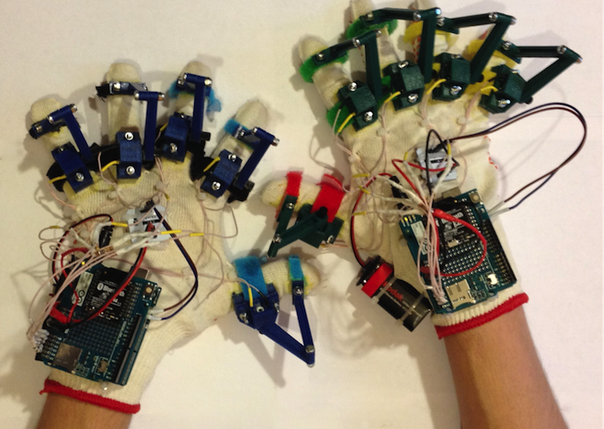
Arduino藍牙手套第一部分-基礎
入門篇:Arduino藍牙手套第一部分 – 基礎
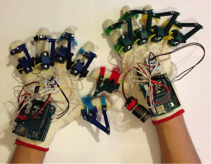
本專案的目的是研發一種能夠檢測出操作員的手和手指方位的裝置,以實現機器人的控制。我們將介紹有關電阻和分壓器的基礎知識。另外,我們還將瞭解如何透過 I2C匯流排從陀螺儀和加速度計獲取測量值,以及如何建立 Arduino–PC藍牙連接。該裝置在積體到 Arduino藍牙手套中之後將會發揮出它的作用。
硬體
- Arduino UNO
- 麵包板
- 電位計 0-10kOhm
- 電阻 10 kOhm
- IMU 感測器
- 電線
- Arduino 無線擴展板
- Xbee USB 適配器
- Bluetooth Bee
- PC 藍牙適配器
- USB A-B 資料線
- 微型 USB 資料線
軟體
- Arduino IDE 1.6.7
- LabVIEW
工具
- 萬用表
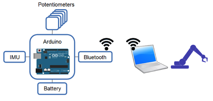
圖1: Arduino藍牙手套專案的基本示意圖
基於Arduino的採集系統組態在用戶的每只手上。Arduino研發板透過測量每個電位計的電阻來獲取手指彎曲(手指彎折)的資訊。在處理了來自慣性測量單元(IMU)的資料後,可以識別出用戶手的方位,該單元包括陀螺儀和加速度計。電池和無線資料傳輸模式使基於 Arduino的採集系統可用作一個可穿戴智慧手套。例如,它可以用作手動控制機器人手臂的通用輸入裝置。
旋轉測量
當旋轉從手指傳遞到電位器手柄時,可以透過測量每個電位計的電阻來識別手指的彎曲。可使用分壓器來測量電位計電阻。如果想要降低電壓並獲得某些固定值,可以在電路中使用分壓器,由兩個或多個電阻組成。
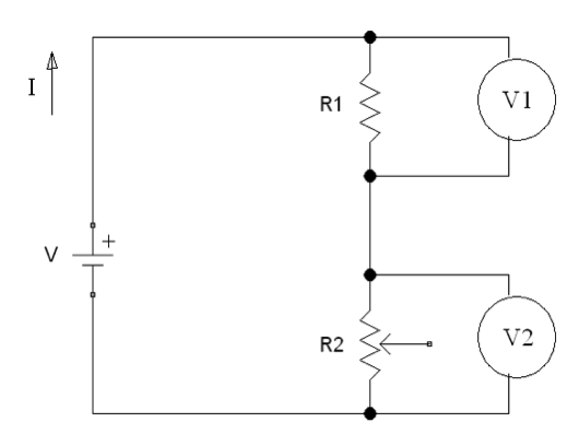
圖2:分壓器電路圖
V 是來自Arduino 5V電源的電壓; I 是 流經電路的電流; R1是具有固定電阻值的電阻; R2 是具有可變電阻的電位計; V1和V2是電壓表。
電壓在電阻R1和R2處均產生壓降。V1和V2之和為V的值。根據歐姆定律:
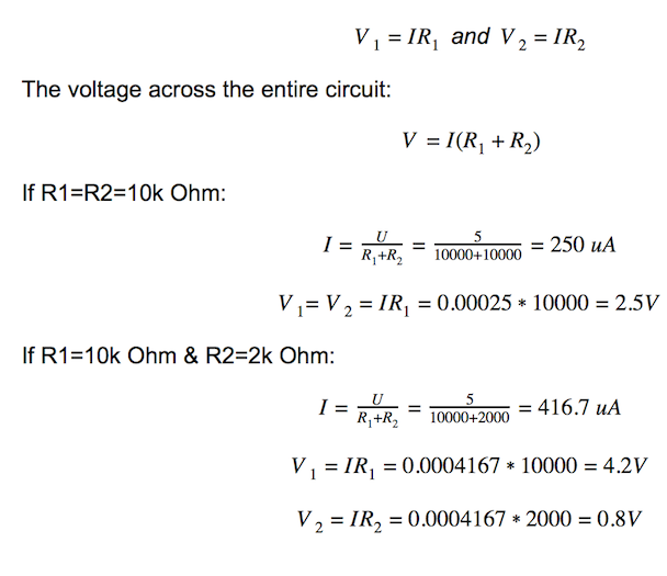
用Arduino類比輸入代替V2電壓表,以測量電位計的電阻。
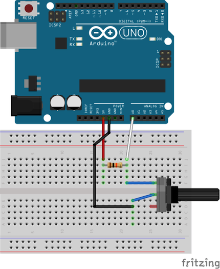
圖3:分壓器電路示意圖
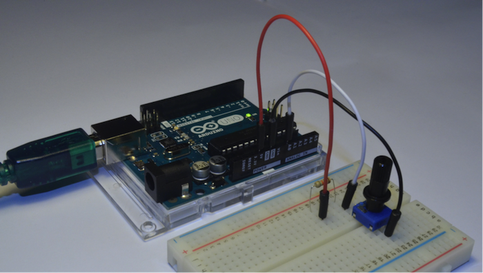
圖4:安裝在麵包板上的分壓器電路
|
1 2 3 4 5 6 7 8 9 10 11 12 |
int sensorValue; void setup() { Serial.begin(9600);// initialize serial communication at 9600 bits per second } void loop() { sensorValue = analogRead(A0);// read the input on analog pin 0 Serial.println(sensorValue);// print out the value you read delay(100); // delay in between reads for stability } |
定向測量
慣性測量單元(IMU)是一種可以測量人體比力和角速度的電子裝置。透過對角速度的連續積分,我們可以獲得安裝有IMU感測器的物體的當前方向。
得益於MEMS技術,IMU感測器開始流行並被廣泛使用。大多數MEMS IMU感測器利用 I2C協議作為將測量結果發送到控制器的主要方式。
您必須為晶片提供電源(V和G),並將資料和時脈引腳(D和C)連接到相應的數位引腳(SDA和SCL),如圖5所示:
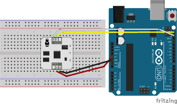
圖5:IMU感測器連接
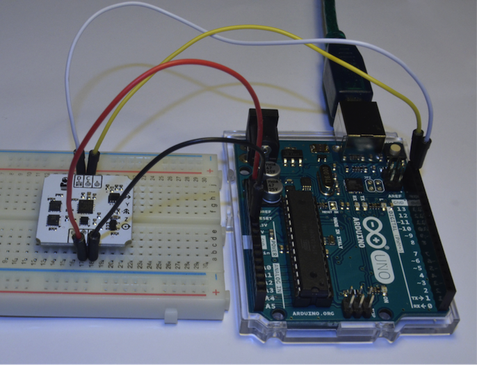
圖6:連接到Arduino研發板的IMU感測器
通常,來自不同製造商的IMU感測器都會具有相同的結構,即所有的MEMS晶片都連接到 I2C匯流排。因此,要從陀螺儀、加速度計和磁力計獲取測量值,您將僅使用這兩個引腳。
我們這裡使用的IMU感測器包含 STMicroelectronics晶片( L3G4200D和 LIS331DLH )。如果您使用包含不同MEMS晶片的IMU感測器,可以更改原始程式碼中的位址使其工作。
現在,讓我們進行測試程式吧!
您需要下載安裝IMU 程式館 (點擊Github上的“View Raw”來下載 IMU_Sensor.zip)。
將.ZIP Library 添加到 Arduino IDE (Sketch >> Include Library >> Add .ZIP Library…)
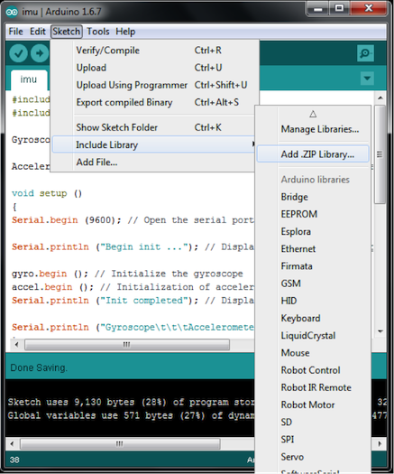
圖7: Arduino IDE上添加.ZIP Library
您將會在 Arduino libraries資料夾中看到 IMU_Sensor程式館(圖8)。現在,我們將使用“#include <imu.h>”測試IMU感測器。
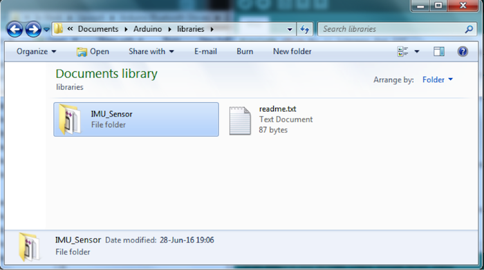
圖8:Arduino libraries資料夾中出現的 IMU_Sensor程式館
|
1 2 3 4 5 6 7 8 9 10 11 12 13 14 15 16 17 18 19 20 21 22 23 24 25 26 27 28 29 30 31 32 33 34 35 36 37 38 39 |
#include <Wire.h> // Library for I²C #include <imu.h> // Library for working with IMU modules Gyroscope gyro; // Create an object to work with Gyroscope Accelerometer accel; // Create an object to work with Accelerometer void setup () { Serial.begin (9600); // Open the serial port Serial.println ("Begin init ..."); // Display a message on the beginning of the initialization gyro.begin (); // Initialize the gyroscope accel.begin (); // Initialization of accelerometers Serial.println ("Init completed"); // Display a message about the successful initialization Serial.println ("Gyroscope\t\t\tAccelerometer"); } void loop () { Serial.print (gyro.readX_DegPerSec ()); // Output angular velocity around the axis X Serial.print ("\t"); Serial.print (gyro.readY_DegPerSec ()); // Output of the angular velocity around the Y axis Serial.print ("\t"); Serial.print (gyro.readZ_DegPerSec ()); // Output of the angular velocity about the Z axis Serial.print ("\t\t"); Serial.print (accel.readX_G ()); // Output of the direction and magnitude of acceleration along the X axis Serial.print ("\t"); Serial.print (accel.readY_G ()); // Output of the direction and magnitude of acceleration along the Y-axis Serial.print ("\t"); Serial.print (accel.readZ_G ()); // Output of the direction and magnitude of acceleration along the Z axis Serial.print ("\t\t"); Serial.println (""); delay (300); } |
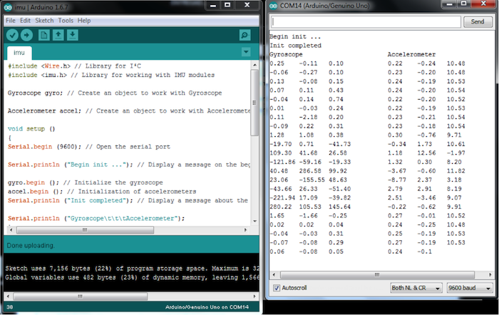
圖9:IMU感測器輸出
無線資料傳輸
可以使用 Bluetooth Bee(無線藍牙BT模組)來建立無線連接。 Bluetooth Bee模組帶有板載天線。它的作用就像一個透明序列埠,可與各種藍牙適配器和藍牙手機配合使用。
為了檢查藍牙模組配置,請將切換置於AT模式。當模組處於AT模式時,使用者或主機微控制器可以透過經序列埠發送預定義的AT指令來對其進行配置。在AT模式下,您可以從BT模組獲取服務資料並更改某些設定(名稱,序列傳輸速率,同位和停止位)。
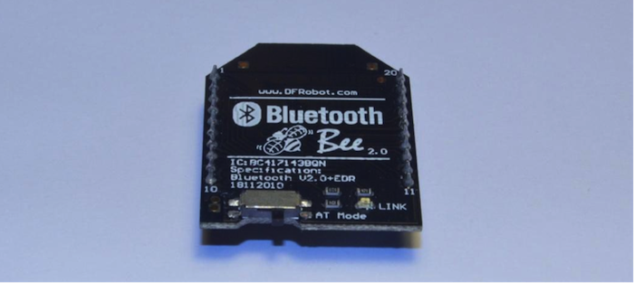
圖10:切換置於AT模式的 Bluetooth Bee
將BT模組和 Xbee適配器堆疊在一起,然後透過微型USB電纜將 Xbee適配器連接到PC。LED燈必須處於打開狀態。
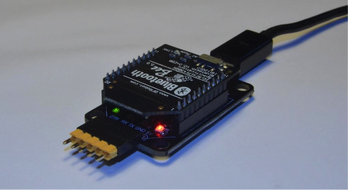
圖11: Bluetooth Bee 放置於 Xbee適配器上
啟動 Arduino IDE, 從Tools >> Serial Port 功能表中選擇與 Xbee適配器對應的COM 埠。
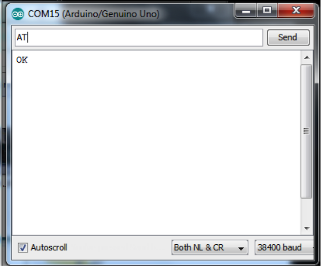
打開 Arduino的序列監視器 (Tools >> Serial Monitor 或者 Ctrl+Shift+M)。如果COM埠沒有正常顯示,請安裝 Xbee USB適配器驅動程式。從相應的選項欄中選擇“Both NL & CR”, “38400”來更改PC的序列設定,以讀取來自 Xbee適配器的資訊,或寫入需要輸入到 Xbee 適配器中的資訊。
發送 “AT” 並接收到 “OK”。
發送 “AT+UART?” 並接收序列設定,如 “9600,0,0”。
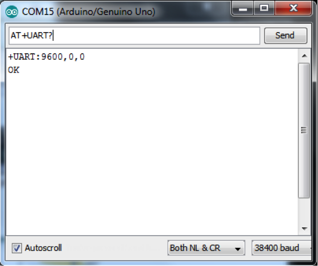
如果您接收到的序列設定不是 “9600,0,0”,那麼發送 “AT+UART=9600,0,0” 指令並接收到 “OK”。
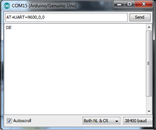
斷路序列監視器,斷開 Xbee適配器與微型 USB資料線和BT模組的連接。不要忘記向左旋轉切換來斷路AT模式。
將 Bluetooth Bee放置在 Arduino無線擴展板上,將 Arduino與USB A-B資料線連接,如圖12所示。
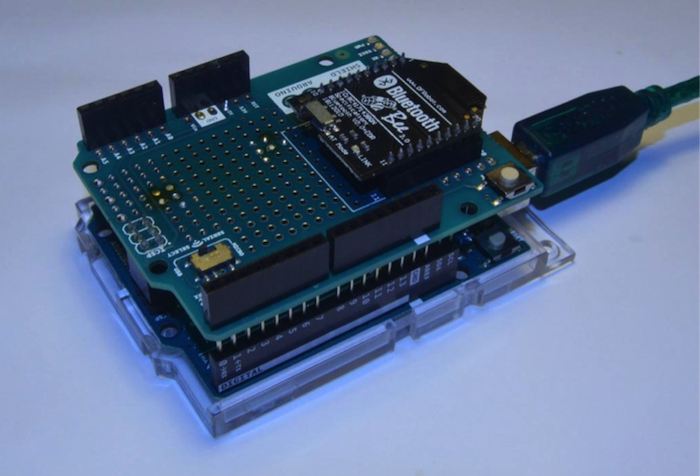
圖12:在 Arduino無線擴展板上的 Bluetooth Bee
完成此步驟後,您將可以使用默認的“我的藍牙裝置”視窗找到您的 Bluetooth Bee。將您的 Bluetooth Bee與預設密碼“1234”配對。請注意連接到您的裝置的是哪個COM埠,在下一步草圖中選擇該COM埠。
這是用於測試藍牙連接的 Arduino草圖。(請注意,當將 Bluetooth Bee 安裝到 Arduino無線擴展板上時,您將無法啟用草圖)。
|
1 2 3 4 5 6 7 8 9 10 11 12 13 14 15 16 17 18 19 20 21 22 23 |
#define LED 13 int pause = 0; // variable to store sent value void setup() { pinMode(LED, OUTPUT); Serial.begin(9600); // open the serial port } void loop() { if (Serial.available() > 0) { // read incoming serial data: String inStr = Serial.readString(); Serial.println("Get Message:"+inStr); pause = inStr.toInt(); } digitalWrite(LED, HIGH); // turn the LED on (HIGH is the voltage level) delay(pause); // wait for a second digitalWrite(LED, LOW); // turn the LED off by making the voltage LOW delay(pause); // wait for a second } |
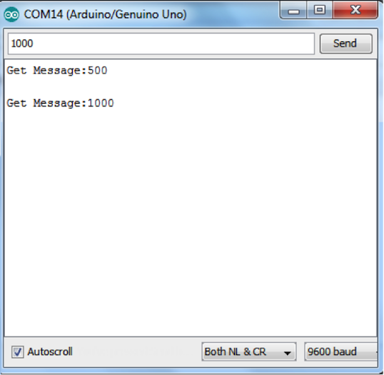
圖13:測試 Bluetooth Bee連接
如果您有任何意見或疑問,請在Google +上給我們留言。請在該主頁繼續關注我們,我們將會儘快發佈更多資訊。


