TFT液晶面板與三軸加速度計的配合使用–第2部分

在第1部分中,我們能夠獲取KX022-1020加速度計的數值並將其顯示到TFT液晶LCD面板上。在第2部分中,我們將展示如何在讀取程式內容的同時控制TFT顯示幕!
今天的電子食譜
預計完成時間:60分鐘
所需零件:
- Arduino 主體 (Arduino UNO R3)
- 羅姆感測器評估套件 http://www.rohm.com/web/global/sensor-shield-support
- TFT 液晶面板 (sainsmart 1.8) https://www.sainsmart.com/sainsmart-1-8-spi-lcd-module-with-microsd-led-backlight-for-arduino-mega-atmel-atmega.html
※ 您可以從以下網站購買羅姆感測器評估套件!
透過Arduino在TFT液晶顯示幕上顯示資料
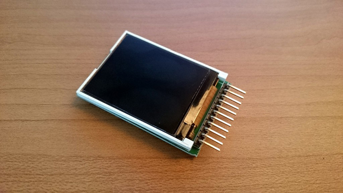
和之前一樣,我們使用SainSmart ST7735R TFT顯示幕。這是一款緊湊的LCD顯示幕,可相容Arduino和Raspberry Pi。該顯示幕具有內建microSD卡插槽,因此除了讀取和寫入資料外,還可以存儲和載入圖像。在本課程中,我們將僅嘗試在該TFT顯示幕上顯示數值。
我們開始吧!首先,將TFT顯示幕與Arduino連接起來。

圖1 SainSmart ST7735R TFT顯示幕

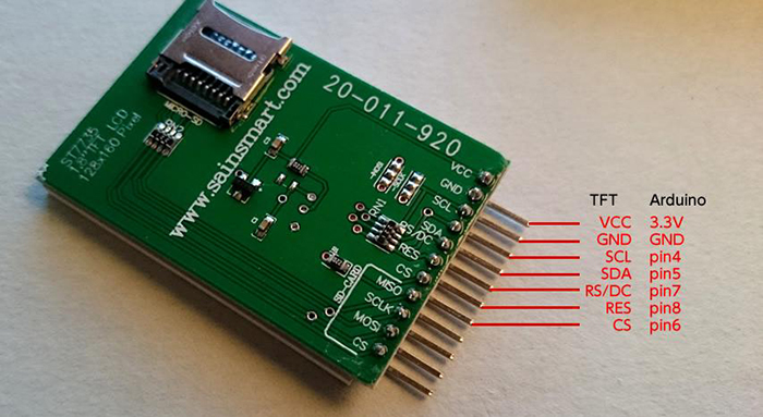
圖2 TFT顯示幕的背面
TFT 引腳定義:
- VCC – 供電電壓
- GND – 地
- SCL – 序列時脈線
- SDA – 序列資料線
- RS / DC – 命令/資料選擇
- RES – LCD 控制器復位
- CS – 卡的片選訊號
將Arduino連至TFT顯示幕之後,我們來運行範例程式。
將TFT顯示幕程式館文件應用於Arduino
正如文章第1部分中提到的,我們需要對程式館檔(ST7735R)進行一些小的修改,以便讓TFT顯示幕相容Arduino系統。
用於Arduino的SainSmart 1.8 ST7735R TFT液晶顯示幕,搭載MicroSD卡槽和LED背光
Raspberry Pi 程式館 (ST7735R V0.2)
上述URL的頁面底部有一個下載連結。按一下頁面上標有 “Download Link” 的連結,下載完整的程式館、範例代碼及文件等。下載完成後,解壓檔並重新編寫必要的檔。
請用能夠編輯文本的編輯器打開 “ST7735.h” ,然後更改下圖所示的部分。您也可以使用Arduino IDE。

更改完成後,用zip再次壓縮 “TFT 18” 目錄,然後在Arduino(或Arduino Create)Add Library中將其作為一個程式館添加;或者將其放置在Arduino安裝目錄的“libraries”目錄下並載入該程式館。
導入程式館之後,請嘗試在範例程式中行動 “TFT 18” – “graphictest” 。
您會看到範例程式的顯示非常流暢。
範例程式 – graphictest
|
1 2 3 4 5 6 7 8 9 10 11 12 13 14 15 16 17 18 19 20 21 22 23 24 25 26 27 28 29 30 31 32 33 34 35 36 37 38 39 40 41 42 43 44 45 46 47 48 49 50 51 52 53 54 55 56 57 58 59 60 61 62 63 64 65 66 67 68 69 70 71 72 73 74 75 76 77 78 79 80 81 82 83 84 85 86 87 88 89 90 91 92 93 94 95 96 97 98 99 100 101 102 103 104 105 106 107 108 109 110 111 112 113 114 115 116 117 118 119 120 121 122 123 124 125 126 127 128 129 130 131 132 133 134 135 136 137 138 139 |
//Pin setting #define sclk 4 #define mosi 5 #define cs 6 #define dc 7 #define rst 8 //Color numbering #define BLACK 0x0000 #define BLUE 0x001F #define RED 0xF800 #define GREEN 0x07E0 #define CYAN 0x07FF #define MAGENTA 0xF81F #define YELLOW 0xFFE0 #define WHITE 0xFFFF #include <ST7735.h> #include <SPI.h> ST7735 tft = ST7735(cs, dc, mosi, sclk, rst); void fillpixelbypixel(uint16_t color) { for (uint8_t x=0; x < tft.width; x++) { for (uint8_t y=0; y < tft.height; y++) { tft.drawPixel(x, y, color); } } delay(100); } void setup(void) { Serial.begin(9600); Serial.print("hello!"); tft.initR(); // initialize a ST7735R chip Serial.println("init"); tft.writecommand(ST7735_DISPON); uint16_t time = millis(); tft.fillScreen(BLACK); time = millis() - time; Serial.println(time, DEC); delay(500); // tft.fillScreen(BLACK); testdrawtext("Lorem ipsum dolor sit amet, consectetur adipiscing elit. Curabitur adipiscing ante sed nibh tincidunt feugiat. Maecenas enim massa, fringilla sed malesuada et, malesuada sit amet turpis. Sed porttitor neque ut ante pretium vitae malesuada nunc bibendum. Nullam aliquet ultrices massa eu hendrerit. Ut sed nisi lorem. In vestibulum purus a tortor imperdiet posuere. ", WHITE); delay(1000); //a single pixel tft.drawPixel(tft.width/2, tft.height/2, GREEN); delay(500); // line draw test testlines(YELLOW); delay(500); // optimized lines testfastlines(RED, BLUE); delay(500); testdrawrects(GREEN); delay(500); testfillrects(YELLOW, MAGENTA); delay(500); tft.fillScreen(BLACK); testfillcircles(10, BLUE); testdrawcircles(10, WHITE); Serial.println("done"); delay(1000); } void loop() { tft.writecommand(ST7735_INVON); delay(500); tft.writecommand(ST7735_INVOFF); delay(500); } void testlines(uint16_t color) { tft.fillScreen(BLACK); for (uint16_t x=0; x < tft.width; x+=6) { tft.drawLine(0, 0, x, tft.height-1, color); } for (uint16_t y=0; y < tft.height; y+=6) { tft.drawLine(0, 0, tft.width-1, y, color); } tft.fillScreen(BLACK); for (uint16_t x=0; x < tft.width; x+=6) { tft.drawLine(tft.width-1, 0, x, tft.height-1, color); } for (uint16_t y=0; y < tft.height; y+=6) { tft.drawLine(tft.width-1, 0, 0, y, color); } tft.fillScreen(BLACK); for (uint16_t x=0; x < tft.width; x+=6) { tft.drawLine(0, tft.height-1, x, 0, color); } for (uint16_t y=0; y < tft.height; y+=6) { tft.drawLine(0, tft.height-1, tft.width-1, y, color); } tft.fillScreen(BLACK); for (uint16_t x=0; x < tft.width; x+=6) { tft.drawLine(tft.width-1, tft.height-1, x, 0, color); } for (uint16_t y=0; y < tft.height; y+=6) { tft.drawLine(tft.width-1, tft.height-1, 0, y, color); } } void testdrawtext(char *text, uint16_t color) { tft.drawString(0, 0, text, color); } void testfastlines(uint16_t color1, uint16_t color2) { tft.fillScreen(BLACK); for (uint16_t y=0; y < tft.height; y+=5) { tft.drawHorizontalLine(0, y, tft.width, color1); } for (uint16_t x=0; x < tft.width; x+=5) { tft.drawVerticalLine(x, 0, tft.height, color2); } } void testdrawrects(uint16_t color) { tft.fillScreen(BLACK); for (uint16_t x=0; x < tft.width; x+=6) { tft.drawRect(tft.width/2 -x/2, tft.height/2 -x/2 , x, x, color); } } void testfillrects(uint16_t color1, uint16_t color2) { tft.fillScreen(BLACK); for (uint16_t x=tft.width-1; x > 6; x-=6) { tft.fillRect(tft.width/2 -x/2, tft.height/2 -x/2 , x, x, color1); tft.drawRect(tft.width/2 -x/2, tft.height/2 -x/2 , x, x, color2); } } void testfillcircles(uint8_t radius, uint16_t color) { for (uint8_t x=radius; x < tft.width; x+=radius*2) { for (uint8_t y=radius; y < tft.height; y+=radius*2) { tft.fillCircle(x, y, radius, color); } } } void testdrawcircles(uint8_t radius, uint16_t color) { for (uint8_t x=0; x < tft.width+radius; x+=radius*2) { for (uint8_t y=0; y < tft.height+radius; y+=radius*2) { tft.drawCircle(x, y, radius, color); } } } |
該TFT顯示幕的主要功能如下所示:
tft.drawPixel(x,y,color); – 在指定位置(x,y)顯示指定顏色(color)的點。
tft.drawCircle(x, y, radius, color); – 在指定位置(x,y)用指定半徑(radius)畫一個圓。
tft.fillRect(x1,y1, x2, y2, color); – 填充指定位置1(x1, y1)至指定位置2(x2, y2)之間的矩形。
tft.drawString(x, y, text, color); – 在指定位置(x,y)用指定顏色(color)顯示文本。
tft.fillScreen(0x0000); – 用指定顏色填充整個顯示幕。
儘管還有其他功能,但是上述主要功能已經能夠滿足幾乎所有我們的顯示要求。
將加速度計的數值繪製成佈局
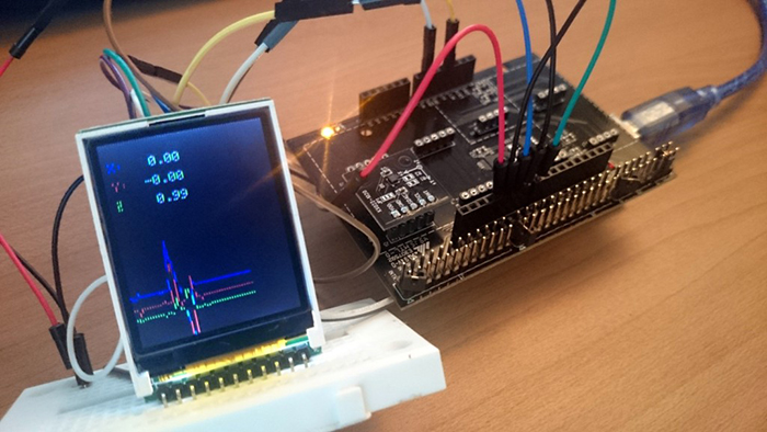
接下來,讓我們在TFT顯示幕上顯示加速度計的數值!基本上,就感測器評估套件而言,我們無需更改TFT顯示幕這邊的連線。只需將KX022-1020加速度計插入感測器研發板即可。

圖3 加速度計和TFT顯示幕
顯示加速度計數值的程式如下:
|
1 2 3 4 5 6 7 8 9 10 11 12 13 14 15 16 17 18 19 20 21 22 23 24 25 26 27 28 29 30 31 32 33 34 35 36 37 38 39 40 41 42 43 44 45 46 47 48 49 50 51 52 53 54 55 56 57 58 59 60 61 62 63 64 65 66 67 68 69 70 71 72 73 74 75 76 77 78 79 80 81 82 83 84 85 86 87 88 89 90 91 92 93 94 95 96 97 98 99 100 101 102 103 104 105 106 107 108 109 110 111 112 113 114 115 116 117 118 119 120 121 122 123 124 125 126 127 128 129 130 131 132 133 134 135 136 137 138 139 140 141 142 143 144 145 146 147 148 149 150 151 152 153 154 155 156 157 158 159 160 161 162 163 164 165 166 167 |
#include <Wire.h> #include <KX022.h> #include <ST7735.h> #include <SPI.h> // You can use any (4 or) 5 pins #define sclk 4 #define mosi 5 #define cs 6 #define dc 7 #define rst 8 // you can also connect this to the Arduino reset // Color definitions #define BLACK 0x0000 #define BLUE 0x001F #define RED 0xF800 #define GREEN 0x07E0 #define CYAN 0x07FF #define MAGENTA 0xF81F #define YELLOW 0xFFE0 #define WHITE 0xFFFF ST7735 tft = ST7735(cs, dc, mosi, sclk, rst); KX022 kx022(KX022_DEVICE_ADDRESS_1E); int _cnt = 0; //Graph initial position int _xc = 120; int _yc = 130; int _zc = 140; void fillpixelbypixel(uint16_t color) { for (uint8_t x=0; x < tft.width; x++) { for (uint8_t y=0; y < tft.height; y++) { tft.drawPixel(x, y, color); } } delay(100); } void setup(void) { byte rc; Serial.begin(9600); while (!Serial); Wire.begin(); tft.initR(); // initialize a ST7735R chip rc = kx022.init(); tft.fillScreen(BLACK); 1.DEVICE PLUS testdrawtext("DEVICE PLUS!!", WHITE,25,50); delay(1000); tft.fillScreen(BLACK); } void loop() { //KX022 byte rc; float acc[3]; //2.Acquire accelerometer values rc = kx022.get_val(acc); if (rc == 0) { Serial.write("KX022 (X) = "); Serial.print(acc[0]); Serial.println(" [g]"); Serial.write("KX022 (Y) = "); Serial.print(acc[1]); Serial.println(" [g]"); Serial.write("KX022 (Z) = "); Serial.print(acc[2]); Serial.println(" [g]"); Serial.println(); //Convert float type to char type char xVal[10]; dtostrf(acc[0], 5, 2, xVal); char yVal[10]; dtostrf(acc[1], 5, 2, yVal); char zVal[10]; dtostrf(acc[2], 5, 2, zVal); //Convert to TFT liquid crystal //tft.fillScreen(BLACK); tft.fillRect(0,0, 120, 60, BLACK); testdrawtext("X:", RED, 5, 15); testdrawtext(xVal, WHITE, 30, 15); testdrawtext("Y:", BLUE, 5, 30); testdrawtext(yVal, WHITE, 30, 30); testdrawtext("Z:", GREEN, 5, 45); testdrawtext(zVal, WHITE, 30, 45); //3.Draw a graph int x = int(acc[0]*100)+120; int y = int(acc[1]*100)+130; int z = int(acc[2]*100)+40; tft.drawLine(_cnt-1, _xc, _cnt, x, RED); tft.drawLine(_cnt-1, _yc, _cnt, y, BLUE); tft.drawLine(_cnt-1, _zc, _cnt, z, GREEN); _cnt++; //Reset to the end of the screen if(_cnt > 120){ _cnt = 0; tft.fillScreen(BLACK); } _xc = x; _yc = y; _zc = z; delay(10); } delay(10); } void testlines(uint16_t color) { tft.fillScreen(BLACK); for (uint16_t x=0; x < tft.width; x+=6) { tft.drawLine(0, 0, x, tft.height-1, color); } for (uint16_t y=0; y < tft.height; y+=6) { tft.drawLine(0, 0, tft.width-1, y, color); } tft.fillScreen(BLACK); for (uint16_t x=0; x < tft.width; x+=6) { tft.drawLine(tft.width-1, 0, x, tft.height-1, color); } for (uint16_t y=0; y < tft.height; y+=6) { tft.drawLine(tft.width-1, 0, 0, y, color); } tft.fillScreen(BLACK); for (uint16_t x=0; x < tft.width; x+=6) { tft.drawLine(0, tft.height-1, x, 0, color); } for (uint16_t y=0; y < tft.height; y+=6) { tft.drawLine(0, tft.height-1, tft.width-1, y, color); } tft.fillScreen(BLACK); for (uint16_t x=0; x < tft.width; x+=6) { tft.drawLine(tft.width-1, tft.height-1, x, 0, color); } for (uint16_t y=0; y < tft.height; y+=6) { tft.drawLine(tft.width-1, tft.height-1, 0, y, color); } } void testdrawtext(char *text, uint16_t color,int x,int y) { tft.drawString(x, y, text, color); } void testfastlines(uint16_t color1, uint16_t color2) { tft.fillScreen(BLACK); for (uint16_t y=0; y < tft.height; y+=5) { tft.drawHorizontalLine(0, y, tft.width, color1); } for (uint16_t x=0; x < tft.width; x+=5) { tft.drawVerticalLine(x, 0, tft.height, color2); } } void testdrawrects(uint16_t color) { tft.fillScreen(BLACK); for (uint16_t x=0; x < tft.width; x+=6) { tft.drawRect(tft.width/2 -x/2, tft.height/2 -x/2 , x, x, color); } } void testfillrects(uint16_t color1, uint16_t color2) { tft.fillScreen(BLACK); for (uint16_t x=tft.width-1; x > 6; x-=6) { tft.fillRect(tft.width/2 -x/2, tft.height/2 -x/2 , x, x, color1); tft.drawRect(tft.width/2 -x/2, tft.height/2 -x/2 , x, x, color2); } } void testfillcircles(uint8_t radius, uint16_t color) { for (uint8_t x=radius; x < tft.width; x+=radius*2) { for (uint8_t y=radius; y < tft.height; y+=radius*2) { tft.fillCircle(x, y, radius, color); } } } void testdrawcircles(uint8_t radius, uint16_t color) { for (uint8_t x=0; x < tft.width+radius; x+=radius*2) { for (uint8_t y=0; y < tft.height+radius; y+=radius*2) { tft.drawCircle(x, y, radius, color); } } } |
運行上述程式後,顯示幕會將加速度計的數值用佈局顯示出來。
該程式流程摘要如下:
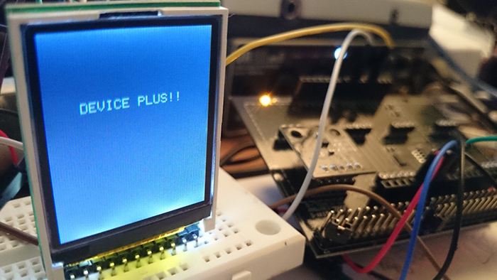
- 啟動時顯示“DEVICE PLUS !!”字元
- 獲取加速度計的數值並將其轉換為整數
- 根據數值顯示佈局和文本
每一訊框我們給x軸加1,以便從左到右繪製佈局。
當畫面到達120px顯示幕的邊緣時,程式會用drawrect清除佈局。螢幕上方的數位以相同的方式透過drawrect進行每訊框更新。
至此,利用TFT液晶顯示幕顯示加速度計的數值並繪製相關佈局的課程就結束了!我們還可以考慮研發更多的附帶專案。比如,我們可以將此TFT顯示幕與Arduino Pro Mini組合在一起,製作具有小型遊戲功能的手錶等;還可以利用感測器評估套件中的不同感測器來製作資料記錄器。


