AC-DC|Design
Designing Isolated Flyback Converter Circuits: Selecting Critical Components ? MOSFET related – 2
2016.06.23
Points of this article
・The circuits for the control of switching transistors (MOSFET) operation are based on the specifications of the power supply IC.
・Power supply IC datasheets provide circuits and component values determination methods; such information should be consulted in designing a circuit.
table of contents
Having finished the selection of MOSFET Q1 in the section [Selecting Critical Components ? MOSFET related – 1], we now move on to the step of configuring a circuit around the MOSFET.
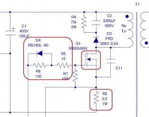
First, let us review the operation of the circuit. The signal from the OUT (PWM output) pin from the IC is adjusted in the D4, R5, and R6 to ensure that the MOSFET Q1 operates properly, and to drive the gate of the MOSFET. The MOSFET Q1 turns the rectified high voltage on and off that was input to the primary side of the transformer T1, and transmits the energy of the high voltage to the secondary side. When Q1 turns on, Ids flows. However, since the current cannot be allowed to flow indefinitely, the R8 is used to detect and limit the current.
In this section, we first determine the circuit (diode D4, resistors R5 and R6) that adjusts the gate drive for the MOSFET. Subsequently, we also determine the current sense resistor R8 that is necessary for current sense and slope compensation.
MOSFET gate circuit, R5, R6, and D4
In order to drive the MOSFET, signal is output from the PWM output pin of the power supply IC. Since an optimal operation cannot be ensured by simply connecting the signal to the gate of the MOSFET, adjustments are needed to be consistent with the circuit and required properties. In concrete terms, the MOSFET’s switching loss and noise must be optimized.
We adjust the on- and off-speeds (rise and fall time) of the MOSFET so that the MOSFET operates in a manner that represents a compromise between switching loss and switching noise. A compromise is needed because switching loss and switching noise are mutually conflicting factors: Increasing the switching speed reduces the switching loss, whereas the greater the switching speed, creating sharp current changes, the greater is the resulting switching noise.
It is difficult to calculate gate circuit constants based on fixed formulas. Therefore, beginning with the values that are shown in the circuit diagrams on the power supply IC datasheet, finally operate them on an actual device to determine whether the rise in MOSFET temperature is within the allowable range, that is, to evaluate the extent of switching loss. In addition, you need to measure the switching noise to see if it is in a proper range.
- When the MOSFET is on, adjust the speed with R5 and R6
- When the MOSFET is off, adjust the speed with R5 through the fast gate discharge diode D4
In the discontinuous mode for the current mode, which represents a selected operation, basically no switching loss occurs when the MOSFET is on, and the loss occurring during off-time becomes predominant. To reduce switching loss when the MOSFET is off, the speed must be increased by reducing the R5; this approach, however, causes sharp current changes, resulting in an increased switching noise. In the example circuit provided in this section, the following data emerge:
- R5=22Ω 0.25W、R6=150Ω、D4:RB160L-60 (Schottky diode 60V/1A)
The diode D4 is used to rapidly discharge the gate charges when the MOSFET is off. A Schottky barrier diode is selected for this purpose by virtue of its low loss and high-speed operation.
As a precaution, since a pulse current flows into the R5, the pulse tolerance of the resistor to be used should be verified.
Current sense resistor R8
The current sense resistor R8 is connected to the source of the MOSFET. One end (for the source) is connected to the CS pin of the power supply IC, and the other end is connected to GND. The CS pin functions through the use of a voltage drop that is generated by the current flowing to the R8 when the MOSFET is on. The resistor performs three functions: limiting the current flowing to the primary side, providing protection against an output overload, and determining slope compensation through the current mode control. For further details on the CS pin, see the Power Supply IC BM1P061FJ Datasheet.
Because it performs multiple functions, the resistor may be subject to restrictions by the primary side inductance of the transformer and by the input voltage. For this reason, the resistor R8 is calculated according to the formula given below, where the values of Ippk and Duty are determined according to [Transformer Design (Calculating numerical values)]. Based on the CS pin voltage standard for BM1P061FJ, the value of Vcs turns out to be 0.4V.

The calculation yields an R8 value of 0.2Ω.
Also, the P_R8 value, which represents the loss due to the sense resistor R8, can be determined according to the following equations:

By taking into consideration the results of the calculations and the pulse tolerance, the value 1W or greater is identified to be an allowable resistor. With regard to pulse tolerance, because for a given power rating the pulse tolerance changes by the structure of the resistor, it should be checked with the manufacturer of the resistor to be used.
Thus, we have determined the values for the components around the MOSFET. Although the approach, requiring empirical evaluations and verifications by means of an actual device and involving more than formula calculations, may lack in clarity, remember that such is not uncommon in the power supply design process.
【Download Documents】Design Example for PWM Flyback Converter
ROHM’s seminar materials provided at the seminar venue. Explanation how to design a flyback converter using a power supply IC.
List of articles related to the「Designing Isolated Flyback Converter Circuits: Selecting Critical Components ? MOSFET related – 2」
- Overview of Design Method of PWM AC-DC Flyback Converters
- Want are Isolated Flyhback Convertors?
- Isolated Flyback Converter Basics: What is Switching AC-DC Conversion?
- Isolated Flyback Converter Basics: What are Characteristics of Flyback Converter?
- Isolated Flyback Converter Basics: Flyback Converter Operation and Snubber
- Isolated Flyback Converter Basics: What are Discontinuous Mode and Continuous Mode?
- Design Procedure
- Determining Power Supply Specifications
- Choosing an IC for Design
- Designing Isolated Flyback Converter Circuits
- Designing Isolated Flyback Converter Circuits: Transformer Design (Calculating numerical values)
- Designing Isolated Flyback Converter Circuits: Transformer Design (Structural Design) – 1
- Designing Isolated Flyback Converter Circuits: Transformer Design (Structural Design) – 2
- Designing Isolated Flyback Converter Circuits: Selecting Critical Components ? MOSFET related – 1
- Designing Isolated Flyback Converter Circuits: Selecting Critical Components ? CIN and Snubber
- Designing Isolated Flyback Converter Circuits: Selecting Critical Components ? Output Rectifier and Cout
- Designing Isolated Flyback Converter Circuits: Selecting Critical Components ? VCC of IC
- Designing Isolated Flyback Converter Circuits: Selecting Critical Components – IC Settings Etc.
- Designing Isolated Flyback Converter Circuits: Addressing EMI and Output Noise
- Example Board Layout
- Summary
Download Technical Documents
Basic of AC-DC Conversion
Basic studies to understand AC-DC converters and to go designing.
AC-DC
- Basic
-
Design
-
Overview of Design Method of PWM AC-DC Flyback Converters
- Want are Isolated Flyhback Convertors?
- Isolated Flyback Converter Basics: What is Switching AC-DC Conversion?
- Isolated Flyback Converter Basics: What are Characteristics of Flyback Converter?
- Isolated Flyback Converter Basics: Flyback Converter Operation and Snubber
- Isolated Flyback Converter Basics: What are Discontinuous Mode and Continuous Mode?
- Design Procedure
- Determining Power Supply Specifications
- Choosing an IC for Design
- Designing Isolated Flyback Converter Circuits
- Designing Isolated Flyback Converter Circuits: Transformer Design (Calculating numerical values)
- Designing Isolated Flyback Converter Circuits: Transformer Design (Structural Design) – 1
- Designing Isolated Flyback Converter Circuits: Transformer Design (Structural Design) – 2
- Designing Isolated Flyback Converter Circuits: Selecting Critical Components ? MOSFET related – 1
- Designing Isolated Flyback Converter Circuits: Selecting Critical Components ? MOSFET related – 2
- Designing Isolated Flyback Converter Circuits: Selecting Critical Components ? CIN and Snubber
- Designing Isolated Flyback Converter Circuits: Selecting Critical Components ? Output Rectifier and Cout
- Designing Isolated Flyback Converter Circuits: Selecting Critical Components ? VCC of IC
- Designing Isolated Flyback Converter Circuits: Selecting Critical Components – IC Settings Etc.
- Designing Isolated Flyback Converter Circuits: Addressing EMI and Output Noise
- Example Board Layout
- Summary
-
Overview of Design Examples of AC-DC Non-isolated Buck Converters
- What are Buck Converters? – Basic Operation and Discontinuous Mode vs. Continuous Mode
- Selection of Power Supply ICs and Design Examples
- Selecting Critical Components: Input Capacitor C1 and VCC Capacitor C2
- Selecting Critical Components: Inductor L1
- Selecting Critical Components: Current Sense Resistor R1
- Selecting Critical Components: Output Capacitor C5
- Selecting Critical Components: Output Rectifying Diode D4
- EMI Countermeasures
- Board Layout and Summary
-
Introduction
- Design Procedure
- IC Used in Design
- Power Supply Specifications and Replacement Circuit
- Synchronous Rectifying Circuit Section: Selection of Synchronous Rectifying MOSFET
- Synchronous Rectification Circuit Section: Power Supply IC Selection
- Synchronous Rectification Circuit Section: Selection of Peripheral Circuit Components-C1, R3 at MAX_TON Pin, and VCC Pin
- Synchronous Rectification Circuit Section: Selection of Peripheral Circuit Components-D1, R1, R2 at DRAIN Pin
- Shunt Regulator Circuit Section: Selection of Peripheral Circuit Components
- Troubleshooting ①: Case When Secondary-Side MOSFET Suddenly Turns OFF
- Troubleshooting ②: Case When Secondary-Side MOSFET Turns On Due to Resonance Under Light Loading
- Troubleshooting ③: Case When, Due to Surge, VDS2 Rises to Above Secondary-Side MOSFET VDS Voltage
- Comparison of Efficiency of Diode Rectification and Synchronous Rectification
- Points to Note Relating to PCB Layout
- Summary
-
Introduction
- Power Supply ICs Used in Design: Optimized for SiC MOSFETs
- Design Example Circuit
- Transformer T1 Design – 1
- Transformer T1 Design – 2
- Selecting Critical Components: MOSFET Q1
- Selecting Critical Components: Input Capacitor and Balancing Resistor
- Selecting Critical Components: Switch Setting Resistors for Overload Protection Points
- Selecting Critical Components: VCC-Related Components of Power Supply ICs
- Selecting Critical Components: Components Related to Power Supply IC BO (Brownout) Pins
- Selecting Critical Components: Components Related to Snubber Circuits
- Selecting Critical Components: MOSFET Gate Drive Adjustment Circuit
- Selecting Critical Components: Output Rectifying Diode
- Selecting Critical Components: Output Capacitors, Output Setting and Control Components
- Selecting Critical Components: Current Sense Resistors and Components Related to Detection Pins
- Selecting Critical Components: Components for Dealing with EMI and Output Noise
- PCB Layout Example
- Example Circuit and Component List
- Evaluation Results: Efficiency and Switching Waveform
- Summary
-
Overview of Design Method of PWM AC-DC Flyback Converters
- Evaluation
- Product Information
- FAQ